

Photovoltaic systems and solar inverters - avoid pitfalls

Introduction
Two years ago (year 2022) I installed a solar system on my house, and because of shortage of available technicians (and even materials!) I had to do everything myself, including some hardware components. It was an instructive experience from which I've learnt some things that I did not expect to find. So in this two-parts presentation I share with you what I've learnt, with the hope it will be helpful for you.
In this article you'll have the opportunity to understand the various topologies and configurations of photovoltaic
systems, and their differences so you might make an idea of what would be best for you, if ever interested in installing
one, or making further considerations if you already own one.
Then it is discussed the Maximum Power Point: why it exists and how to deal with it.
And finally the solar inverter insides are explored: main typologies, how they work, and potential (even unexpecting) pitfalls.
Videos
These are the links to the related videos:
"Solar system"?
In this article and in the related video I often use the term "solar system", of course not referring to where our
planet Earth resides, but because it is a commonly used colloquial term in place of the more formal and correct
"photovoltaic system".
For stylistic reasons I preferred to stick with this commonly used colloquial term.
Topologies
Large systems of arrays of photovoltaic panels goes beyond the scope of this article, so the photovoltaic systems considered here are those installed in dwelling houses and similar.
The topologies defines the kind of arrangement that affects how power is managed. Referring to the picture below, from top left to right and bottom, we see in order the following topologies: off-grid, on-grid, hybrid and UPS.
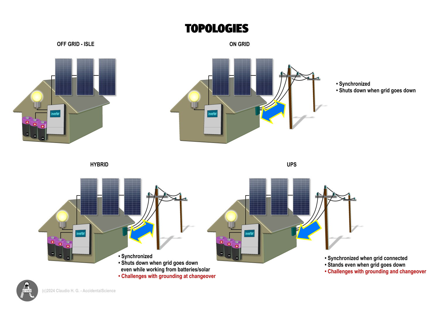
Off-grid
This is an arrangement mainly used by isolated houses where the utility grid is not available or it is too expensive to
bring in place. There is no much to say about this: You are on your own, the whole energy comes from the cosmos :) (our
Sun) that is harvested by solar panels and consumed or stored into the batteries.
Aside the requirement to have a battery charger and management, there are no special requirements for the inverter.
On-grid
This is one of the most common arrangements and the first and only one topology used in solar systems up to recent times.
It is basically an exchange between the grid and your production of energy from Sun. During daytime your system dumps
energy up toward the grid, after the Sun sets you draw energy from the grid. Of course you can consume your own energy
while the Sun is shining and if your consumptions exceed your production capacity then you draw the excess from the grid.
It seems a smart solution but there are hidden caveats from the point of view of the utility grid.
Since the grid must be at any time a perfect balance between all the sources of energy and all the loads, the grid must
be managed with care to avoid excess of energy that may cause the voltage to raise, and consequently causing the intervention
of overvoltage protections, or the voltage to drop if the energy provided by the sources is not enough. Again, the
protections would trip in either case, leading to a black out.
Also when there is an imbalance between sources and loads, even the frequency may be affected which in turn causes a
sort of domino effect making the whole network to collapse.
For this reason every on-grid installation should be notified to the authority that manage the grid (AKA Power System Dispatcher),
and must conform to the specifications put in place by such authority or norms or by law. This is because when you provide power
to the grid you become part of it!
The inverter must:
- Synchronize with the grid's frequency and phase;
- Sense the presence of AC voltage at the grid side to prevent up-supplying power in the case the grid (or just the local line) is down.
Hybrid
This is a relatively recent addition to the previously seen traditional topologies. It is a combination between the
two and provides more flexibility both to the user and to the Dispatcher on the grid side.
As long as the Sun shines you harvest energy storing it into the batteries. Maybe you consume part of it, as well.
When the Sun sets, or there is an overcast day and your system is no longer able to generate enough energy, you can still rely on
the batteries if they have enough stored energy. Ultimately if there's no sunlight nor stored energy in your batteries, you're still
able to draw energy from the utility grid.
And of course, when you have your batteries charged and you do not consume the energy collected by the solar panels, then this
excess of energy is dumped back to the grid.
Needless to say, this system is more complex than the previous ones combined. Not only you have to notify the Dispatcher, but
you also need to cope with the maintenance of the batteries and monitor the overall usage of your solar system to get the most from it.
The inverter must:
- Synchronize with the grid's frequency and phase;
- Sense the presence of AC voltage at the grid side to prevent up-supplying power in the case the grid (or just the local line) is down;
- Sense the batteries, charge and discharge depending by circumstances;
- Also because of the nature of the system that may even work as UPS, the inverter should also manage the neutral-protective earth bonding (more about this in the section Inverter).
UPS
This one comes along with the hybrid topology. UPS stands for Uninterruptible Power Supply, which means that you guarantee your
house a constant source of power even when the grid is down.
With this topology you are more on the side of the off-grid. You never supply energy back to the grid, so you don't have to notify
the authority about the existence of your system into the grid.
Caution: This may vary depending by your local rules, laws and dispatching authority. Check them before taking any decision.
Ideally this topology is best for you if you want to be as autonomous as possible. While the Sun shines you use the energy produced
by your own solar system, even whith cloudy days thanks to the stored energy into the batteries (that in such a case are likely
larger than those used in the hybrid topology). However if both cases of batteries discharged and no sunlight happen you can still
draw energy from the utility grid.
There is also the opposite combination, where your solar system is just in place to supply energy in case of emergency, but it is
kind of waste of money for obvious reasons.
In this topology the inverter must:
- Synchronize with the grid's frequency and phase before it connects to draw energy;
- Sense the presence of AC voltage on the grid side to know if it is an available source of energy in case of neither solar power and battery energy is available;
- Sense the batteries, charge and discharge depending by circumstances;
- Manage the neutral-protective earth bonding (more about this in the section Inverter).
Inverter-Panels Configurations
Once you decided what's best for you as topology, you can now choose from different configurations. Each one has pros and cons.

We have five main possible configurations. The Individual (top left on the picture above) is the most expensive even though capable to provide the best
Maximum Power Poin (MPP) among the other configurations. Though because each inverter has its own efficiency the final result could
be less attractive than it seems at first glance.
Then we have the Branch configuration. This is offer a good, acceptable MPP but it is clearly an expensive configuration that suit
most large installations.
At the bottom side of the picture above are listed three flavours of the same concept: a Central Inverter that works with one or more stings
(a string is an array of panels connected together in series).
With just one single string, which is the most commonly used configuration, we get a good compromise between efficiency
and MPP tracking, with a reasonable cost. The alternative Central Inverter-Multiple MPP (center bottom) is an inverter
that is able to host two, and sometimes three strings, each one with its onw MPP tracking circuit. It is the best option
when it comes to handle multiple strings. It is slightly more expensive than the single Central Inverter and it is much
less expensive than the Branch Inverter configuration.
Finally the Central Inverter Parallel Strings with diodes while is the cheaper solution it is also the worst about MPP tracking.
For the purpose of this presentation the Central Inverter with one string, one of the most commonly used configuration, is considered.
Full Hybrid Photovoltaic System Overview
I've choose to show the full Hybrid Topology with a Central Inverter-Single String configuration because it comprises all possible combinations.
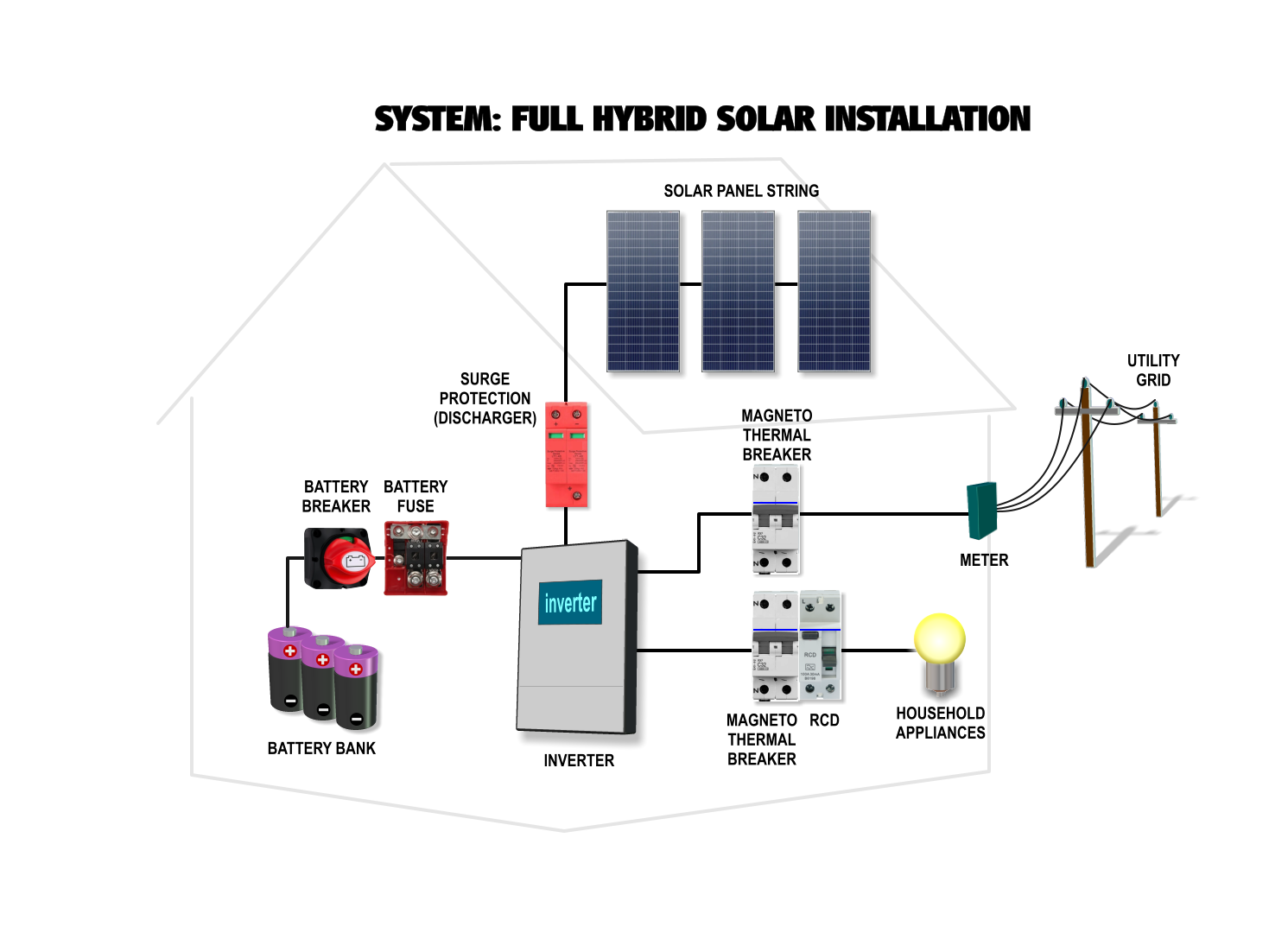
The system is pretty straighforward: we have the string of solar panels connected in series that goes to a surge protection discharger.
This is important to prevent damages caused by EMPs or lightnings. Then we have the batteries with their breaker and fuse box.
The meter must be bidirectional, in the case of UPS (or Off-grid) topology there is no need to change the meter. This however is a
Power System Dispatcher's business, and you should check your local laws and rules about this point.
On the side of your hose you need a magneto-thermal breaker at the input (or exchange) side of the inverter, and the usual magneto-thermal
breaker and RCD (Residual Current Device) on the output side of the inverter that goes to serve your home.
Maximum Power Point
Because of the nature of the cells and of the photovoltaic panels, it is not always possible to get the maximum power out of them.
Here a simplified explanation. Photovoltaic, silicon based cells are made by junction of N and P materials where on one side one
electron is on the valence band and on the other side a hole (where an electron could go) is present in the atoms that form the layer.
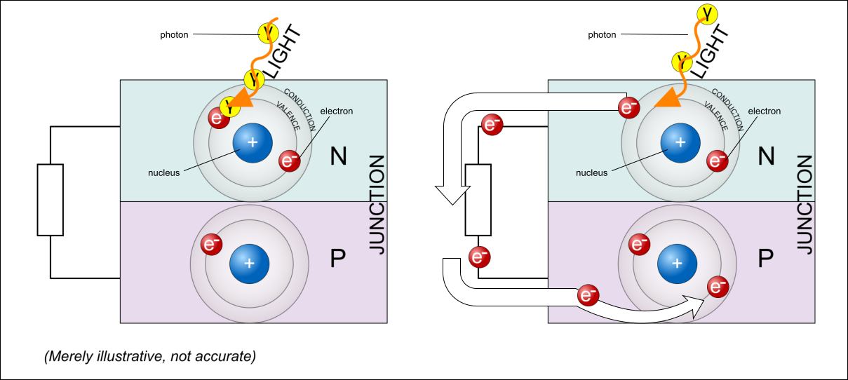
When photons hit the electrons, they excite the electrons that move from the valence band to the conduction band, at which point they
can freely move outside the junction. So if a circuit is connected to the junctions the electrons would move across that circuit to go
where holes are available on the other side of the junction.
If electrons can't find a way to flow out and go to the holes, eventually they goes back to the valence band and the acquired energy
is lost as heat. This hindrance could be caused by internal resistances that opposes the movement of charges (some of them).
It should be noted that those "internal" resistances are not only inside the cell but also inside the panel itself because of the
conductor used in the panels and the shunt resistance inside the cell itself that make the electrons to "leak" across the junction.
These resistances reduce the overall efficiency of the panel and limit the maximum power the panel can output. Also because this depends
by temperature and solar irradiation too (how much electrons are excited and promoted to the conduction band) we have a combined effect.
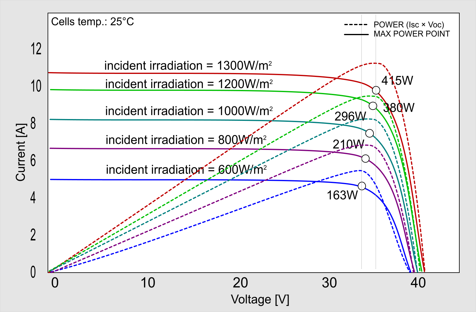
This is a tradeoff between the maximum current that can be achieved at short circuit, and the maximum voltage that can be achieved at open circuit. (See curves above).
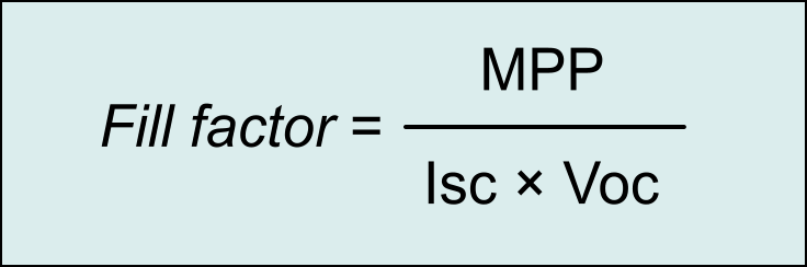
The ratio between the maximum theoretical power, which is given by the short circuit current (Isc) times the open circuit voltage (Voc) and the actual maximum power point (MPP) is what is called the fill factor.
So some kind of circuit must be used to catch the point at which the power is at its maximum.
How Solar Inverters Work
So it's time to have a look at how solar inverters satisfy all the requirements we've seen above. But also some caveats and potential issues.
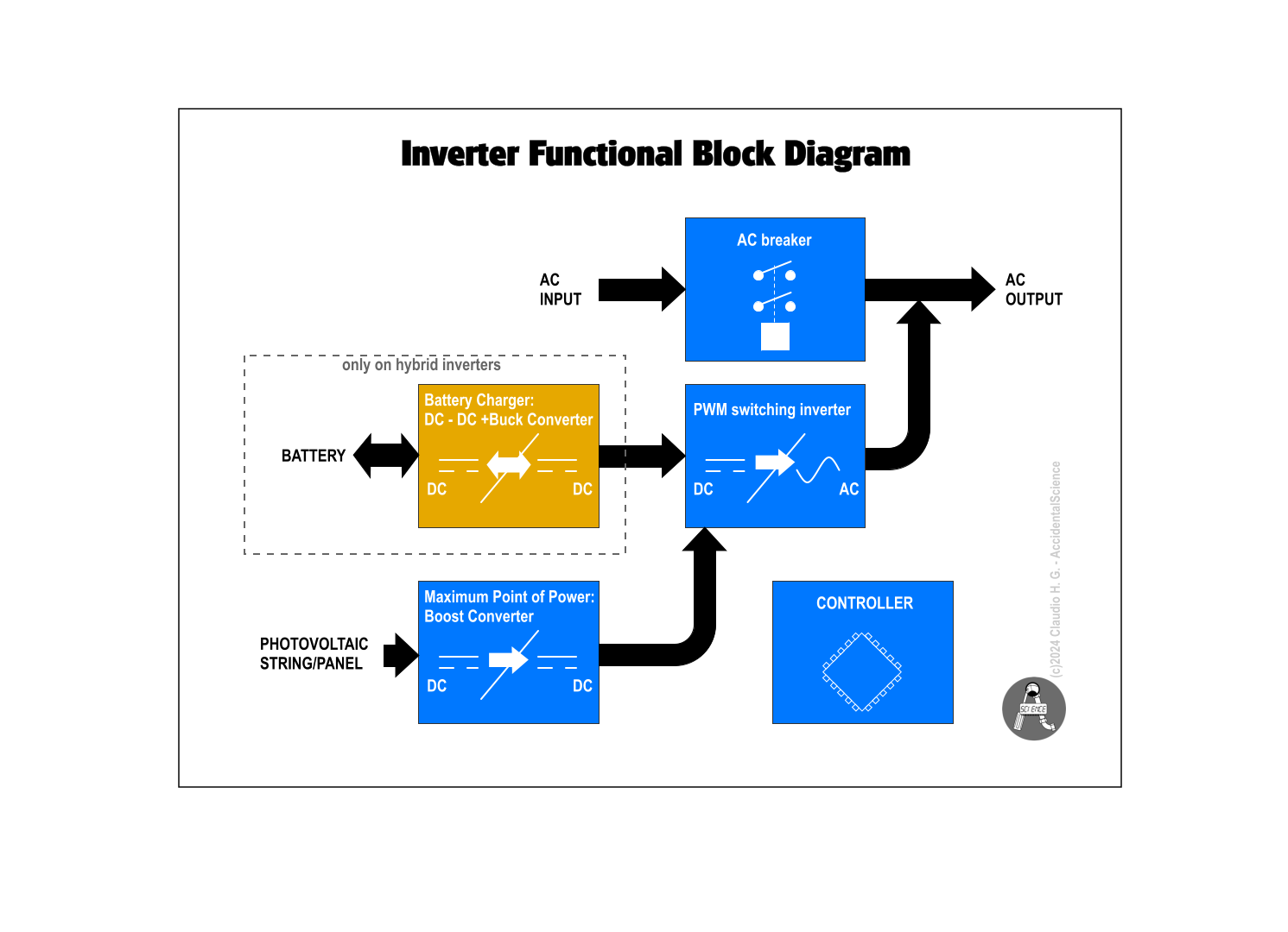
This is a functional diagram of a typical (hybrid) inverter. On top we see the AC Connect relay that separates the AC input from the AC output.
It is controlled by the internal controller (on the bottom-right corner) of the inverter, and closed when the inverter can dump energy to the
grid or need to draw energy from the grid.
The core part of the inverter is the PWM switching that generates the sine wave through pulse width modulation.
At the photovoltaic input there is a boost converter that may rise the voltage coming from the panels to provide enough voltage to the internal
bus that feed the PWM switching section, and adjusting to the maximum power point that is monitored by the controller of the inverter.
On hybrid (and Off-grid) inverters, the battery charger and management is also present. Here a buck converter reduces the voltage to a fixed
point that is then used by a DC to DC via high frequency transformer that makes the current to and from the batteries to flow in both directions.
Basic transformerless inverter
So we can now explore what's inside of the inverter.
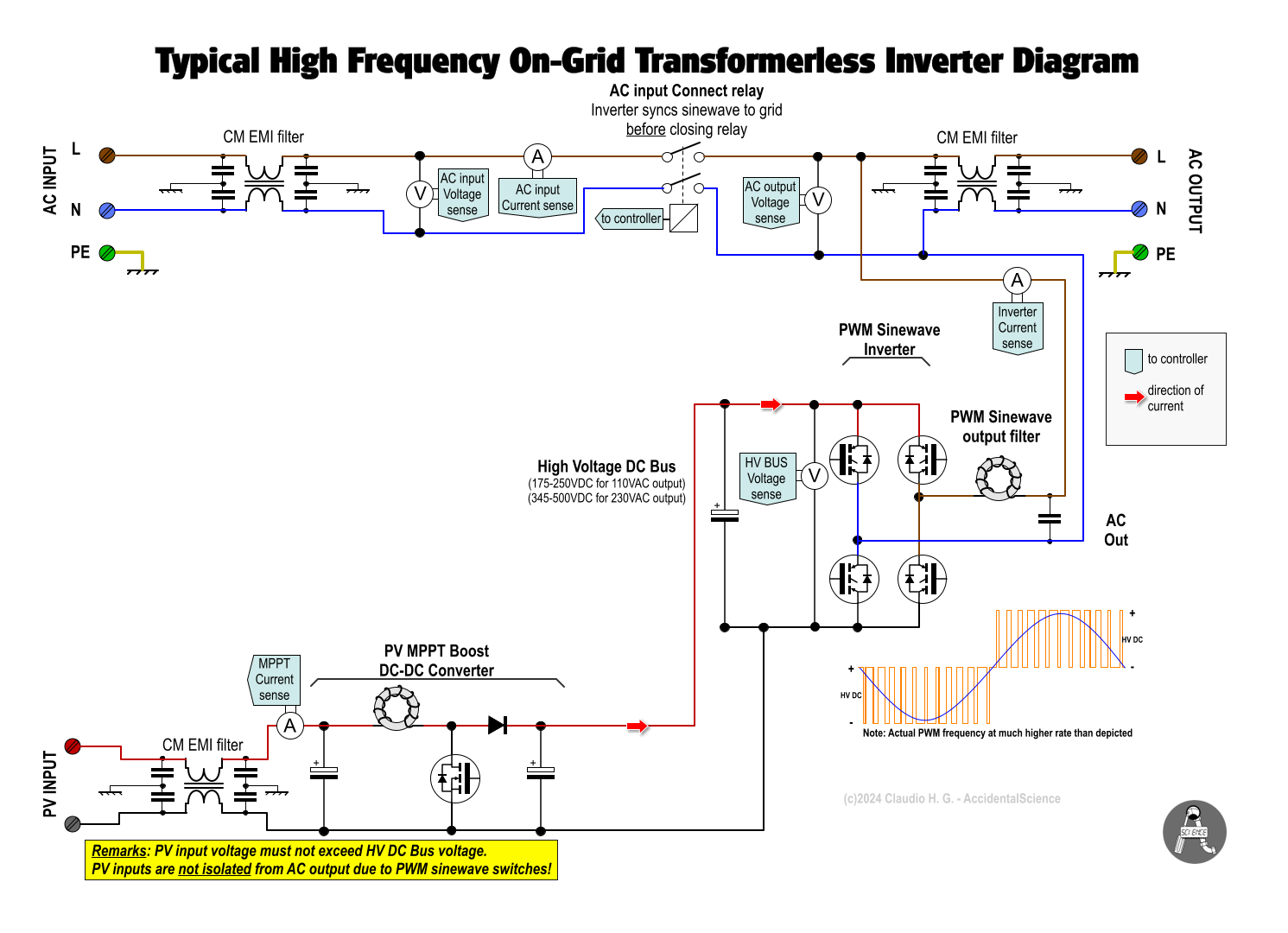
Here we can see three EMI filters that are inserted at the AC input, output and PV input. This is because inverters generate a lot of noise.
Voltage and current sense allow the controller to monitor the AC input voltage and do the required synchronization and frequency generation.
The grid's voltage is mirrored and used to drive a waveform generator that controls the switchers through Pulse Width Modulation.
An illustrative depiction is given at the bottom of the diagram to show how the PWM works. The PWM is shown in orange and the resulting sine
wave is superimposed in blue. Please note that the chopping frequency is much higher than depicted.
The business of the controller is to keep in balance the voltage at the AC output to the nominal voltage and in relation to the voltage at
the AC input. Monitoring the current it determines if the inverter is feeding back or drawing down energy to or from the grid.
This is easily achieved by comparing the sign of the current in relation with the sign of the voltage:
( V+ I+ | V- I- ) = drawing current; ( V+ I- | V- I+ ) = dumping current.
It also important to check the synchronization with the grid's frequency and phase, and the presence of the AC input before supplying back energy. This last point is less trivial and it is a technique that each manufacturer keep restricted. The AC Connect relay is there for these very reasons: isolate the inverter while the inverter is not yet in sync and if the grid is down.
On the lower left corner of the diagram we can see the boost converter. It is formed by the capacitors, the inductor, diode and MOSFET.
Its function is to raise the voltage coming from the panels to meet the minimum requirements of the high voltage DC internal bus.
If there is a cloudy day the panels will not generate much energy, so not enough electrons could be "promoted" to the conduction band.
In addition attempting to draw current is affected by the internal resistance. Thus the boost converter try to compensate these losses.
The PWM switchers are typically a H-Bridge configuration made with MOSFETs or IGBTs.
Limits
Obviously because a boost converter cannot reduce the voltage it is clear that the maximum voltage at the PV input should never exceed the maximum allowed voltage of the HV internal DC bus.
Also it should be noted that because the PWM switcher transistors of the inverter are galvanically connected with the AC, there is no isolation
between the AC and the DC side, including the input of the solar panels!
This is a factor that has implications, as we will see later on.
Isolated inverter

In this diagram you can notice that the main, and only difference over the one you've seen before is that here there is a transformer
connected between the AC line and the PWM switchers. This provides isolation between the AC and DC sides. However transformers are expensive
and have losses. Because inverters play on the maximum efficiency, even a few percent of losses is important.
So these combined factors, cost and efficiency, led most of the manufacturers to drop this transformer in favour of transformerless inverters.
Hybrid inverter

Finally this diagram shows a typical hybrid inverter (used also for Off-grid and UPS topologies). You can notice that the main difference is the
section related to the battery. The first element is a buck converter, that is formed by the MOSFET, inductor, diode and capacitors, right from the
HV DC internal bus. This reduces the voltage when the DC bus reaches the maximum voltage (when the sun shines really bright) to a fixed point required
by the DC-DC converter through HF transformer that follows. This DC-DC converter is bidirectional. Look at it as if it were just a transformer.
The switchers commutate in sync on the two sides, at a fixed frequency, so the transformer works with an alternating current. As you know, transformers
"move" energy on both directions.
So when the battery is charged and provides power to the inverter a current flows in that direction (the red arrows indicate the direction the current
could take). In such a case the MOSFET of the buck converter is always on, as it has nothing to buck, so the current can flow through it freely.
On the other hand, when the battery needs to be charged the power comes from the HV DC bus and the buck converter reduces (if necessary) the voltage at
the point necessary to charge the battery, following its charge curve.
N-PE Bonding
Another important difference is the PE-N bonding. This is a contact that bonds the neutral with the Protective Earth (PE, or simply "ground").
This is important because when the AC Connect relay opens the output neutral wire would become floating. On TT and TN system the neutral must be always
bonded to ground at the entrace, before the RCD. So this relay do this task.
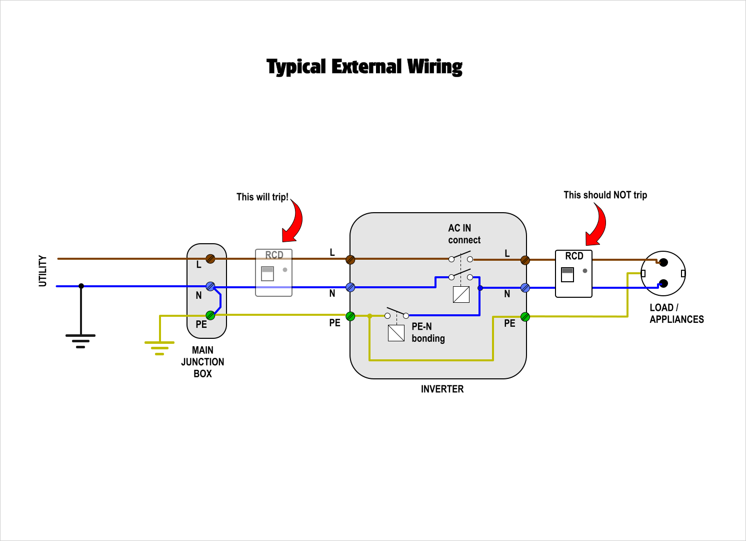
One important consideration is that because the neutral must never be floating, when the AC Connect relay closes again after it was open for a brief
moment the PE-N bonding relay still remains closed. This may cause troubles (as I've discovered) if you keep the main RCD at the entrace after the mains
junction box. An RCD is mandatory at that point, but it would keep tripping at the conditions mentioned above.
Even though the neutral is connected at the junction box, a current may still flow through the neutral in particular if long wires run from the junction
box and the inverter, and there is some load that draw current at its output. This current if it is diverted through the PE line, as it happens when both the
AC Connect relay and the PE-N bonding relay are closed, then the RCD will trip!
The Unexpected Voltage
As a final consideration let's see what happens with a non-isolated inverter when we look at the voltage at the PV input. Because while modulating the switchers one of the transistor keeps the AC live alternalively connected to the HV DC bus negative or the HV DC bus positive, at the PV input you may read an unexpected voltage of approx. 310Vp in respect to PE/ground. (See oscillogram below)
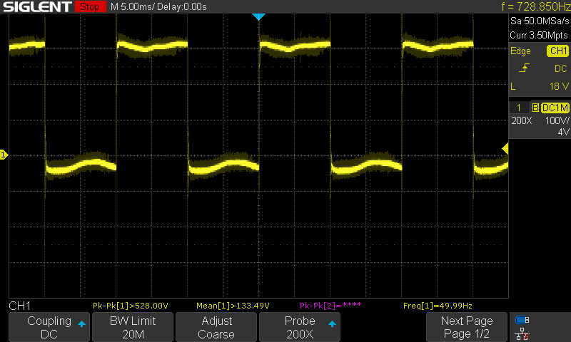
That is what I've measured at the PV input of my transformerless hybrid solar inverter.
What's more is that solar panels have a parasitic capacitance between the edge of the cells and the frame. As shown in the picture below (the red lines that represent
the capacitances).
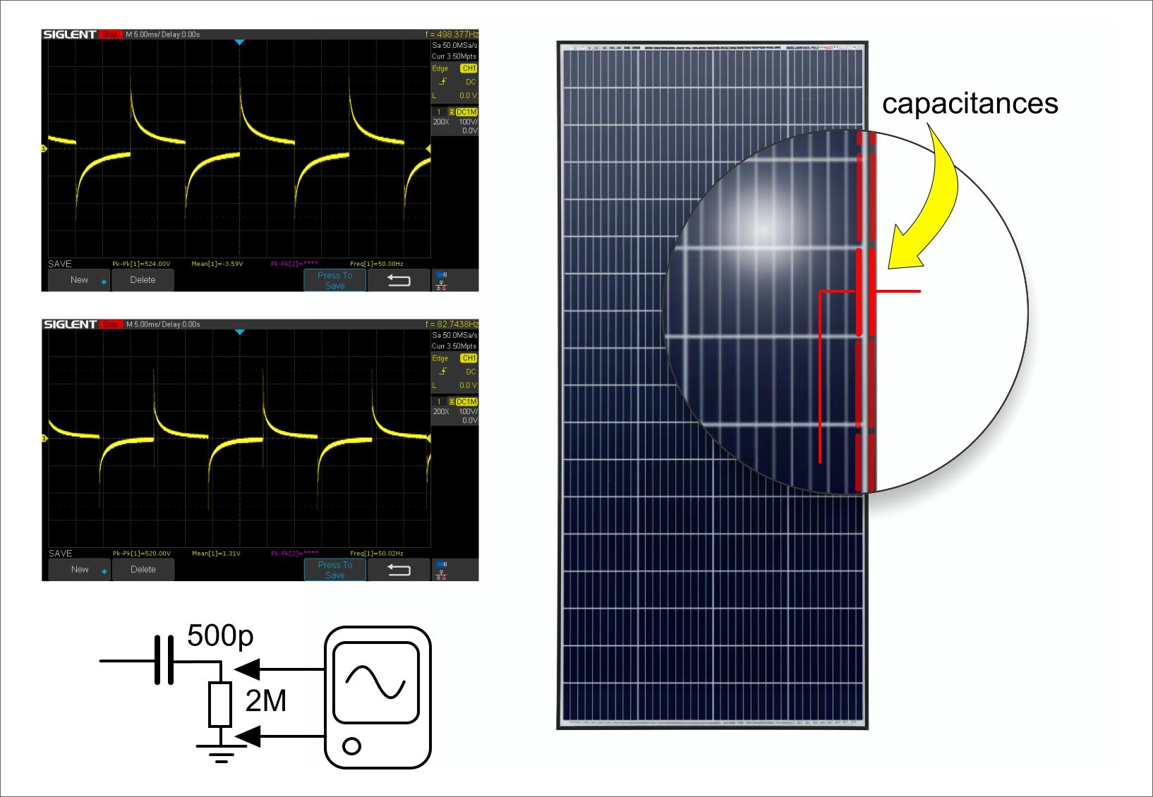
Measuring on two different strings of four panels, between the frame's panel and ground I've got the waveforms that you can see here. Because the measure was made
having a total resistance of about 2 MΩ across the frame and ground, I've been able to calculate the capacitance that resulted of 500pF (rounded value).
This means that if you connect the frames directly to ground a leaking current may flow through the panels!
This was an unexpected finding that went from a chain of conditions, starting from the fact that the inverter is not isolated.
Thanks for reading.
Don't miss next post
Subscribe to stay up to date when new articles, videos or other contents are available.
RELATED ARTICLES
RECENT ARTICLES
 Subscribe
![[Valid Atom 1.0]](../valid-atom.png "Validate my Atom 1.0 feed")