

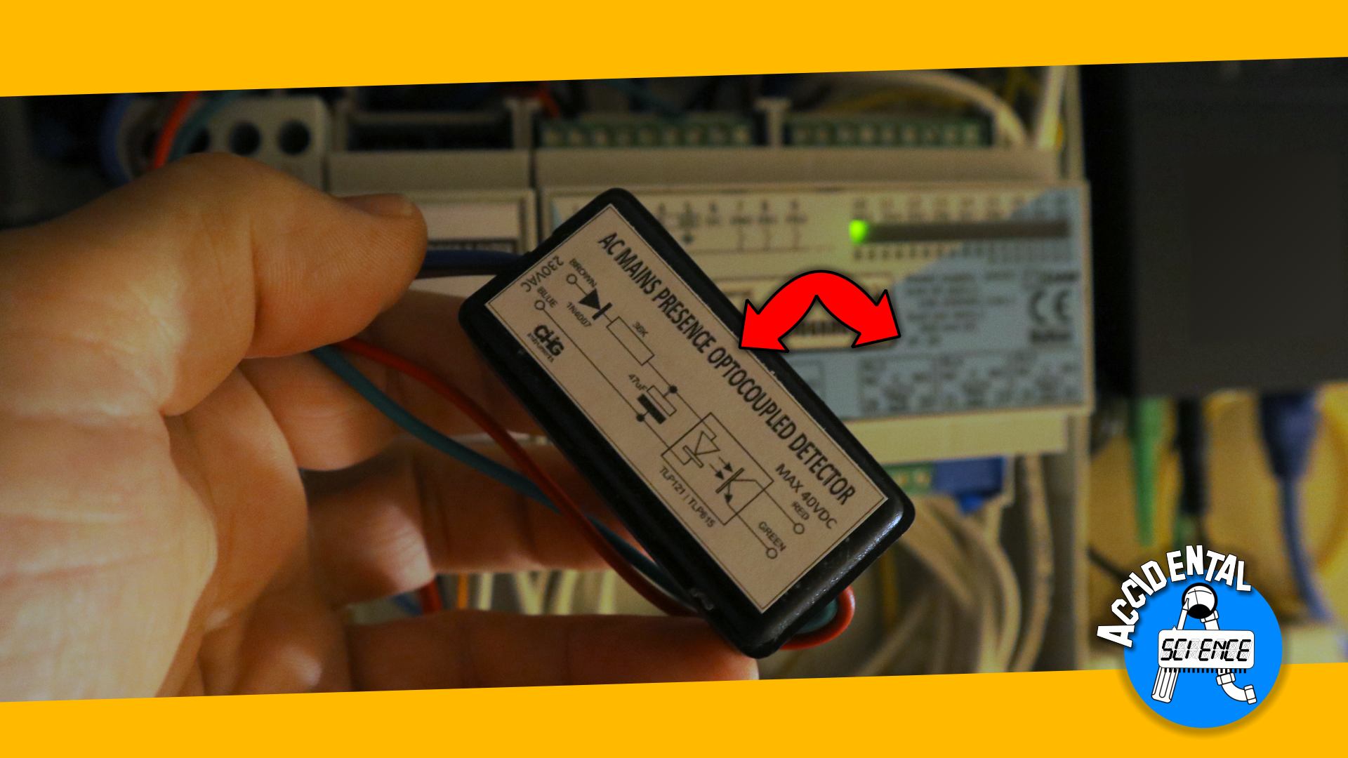
AC Mains Insulated Detector

This is a very simple project that, with a handful of components, can be easily made even by a novice.
⚠ CAUTION: Operating at mains voltage could be dangerous and even fatal. Be careful of what you do and follow the guidelines for working at this voltage and power. Remember, if you replicate the project you will do at your own sole risk. I won't take any liability for damages or injuries, direct or indirect or consequent, due to wrong or improper handling and/or misconstruction/misunderstanding of the circuit and its intended use.
Applications
This circuit can be used to detect when the mains voltage is up (or vice versa when it is down), and safely drive the input of a PLC or a microcontroller, such as Arduino, that is powered ad very low voltage, typically 24V for PLCs and 5VDC for Arduino or other microcontrollers.
Because we use the output of the optoinsulator, as an open collector circuit, it can be used as a switch to convey the required low voltage to the input of the device you use. The logic of the controller determines what to do either when the mains power is up or down.
The optoinsulator used in the circuit is the core component that provides for the transmission of the information while offering good isolation. The component used in this circuit is a TLP121 optoinsulator. Manufactured by Toshiba, they state that it can guarantee insulation for a voltage up to 3750 VAC RMS for 1 minute.
The circuit
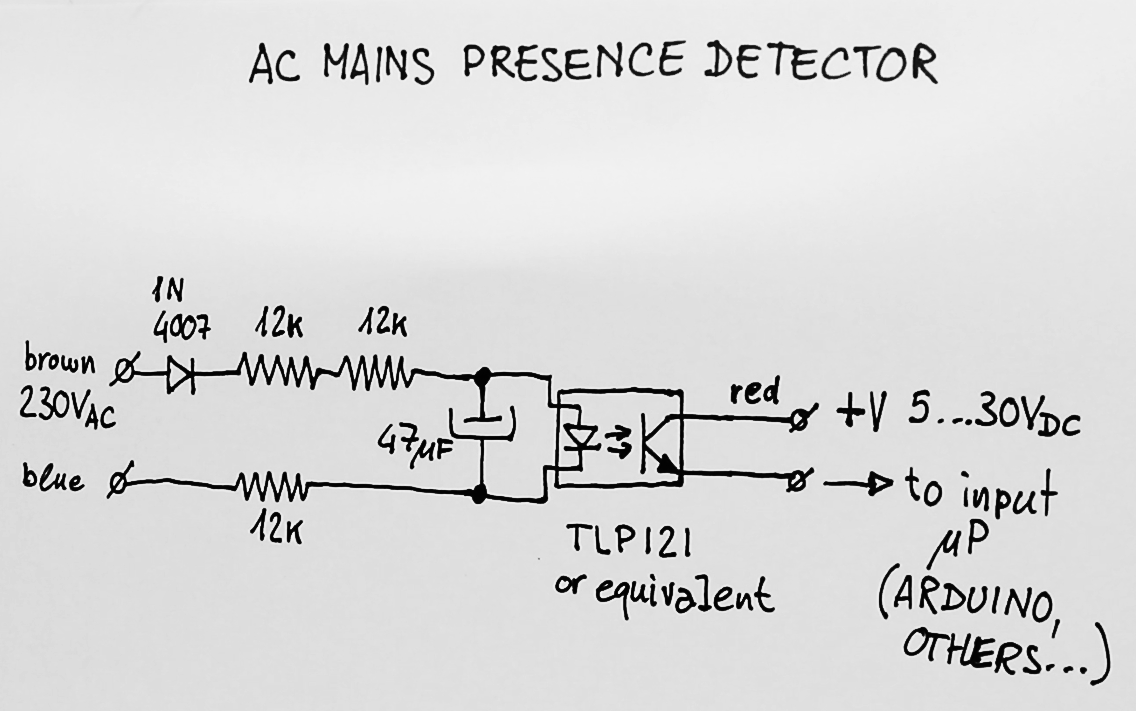
As you can see the circuit is pretty straightforward. Three resistors provide for the necessary voltage drop, and
a capacitor levels the voltage at the emitter of the optioinsulator.
If we look at the specification given by Toshiba, they recommend to feed the emitting diode with 16mA with a voltage
of 1.15V, and a maximum reverse voltage of 5V.
Looking at the circuit we can see that the tree resistors are connected in series, and form a grand total resistance
of 36KΩ. With a voltage of 230VAC RMS you have a peak of 325V, this voltage divided by the resistance gives us
a current of 9mA, which is slightly below the recommended value stated by Toshiba. The specifications tells us that
with 10mA of collector current and 10mA of current at the emitting diode, the voltage drop between the collector and
emitter of the output transistor is less than 1V. So we have plenty of room to drive an Arduino.
Now you may wonder what happens when the voltage at the mains side reverses. In this case the current is stopped by the
1N4007 diode so the reverse limit of 5V that the emitting diode has do not causes excess in current that may lead to the
destruction of the optoinsulator. Also this rectify the current so the 47μF capacitor can level the voltage that
feeds the emitting diode, making sure that the output of the optoinsulator stay on as long as the input mains voltage
is up. This capacitor can be selected for a voltage of less than 20V.
The time constant is:
τ = 36 KΩ ⋅ 47 μF = 1.7 seconds
In reality because we have a continuous drain of current due to the emitting diode, the actual time is about half or 800ms.
This time allows to ignore short glitches that could normally happen when the utility grid perform switches. In EU this
is regulated to be shorter than 300ms, so we have a margin of a little less than three times.

What if I am on a 110V grid?
Simply let's recalculate the resistors to adapt the circuit for a 110V grid. We have to be sure that the emitting diode receives the required current of about 10mA. So:
Rtot = ( 110V ⋅ √2 - 1.85V) / 0.01A = 15325 Ω
The 1.85V is the sum of the voltage drop at the 1N4007 diode and the TLP121's emitting diode.
15325 / 3 gives 5108, and the closest common value is 5100 Ω, that is the value the three resistors must have.
Also, the capacitor should be replaced to keep the same time, so in this case the closest common value of capacitance
is 100 μF.
Why three resistors?
¼ W resistors typically have a maximum voltage of 200V, sometimes even less. To keep a good margin each resistor should be subject to no more than 100...150V so having three resistors allow to divide the voltage preventing the risk of arcs across a single resistor.
Watch the video
Don't miss next post
Subscribe to stay up to date when new articles, videos or other contents are available.
RELATED ARTICLES
RECENT ARTICLES
 Subscribe
![[Valid Atom 1.0]](../valid-atom.png "Validate my Atom 1.0 feed")