

Capacitive Water Level Sensor
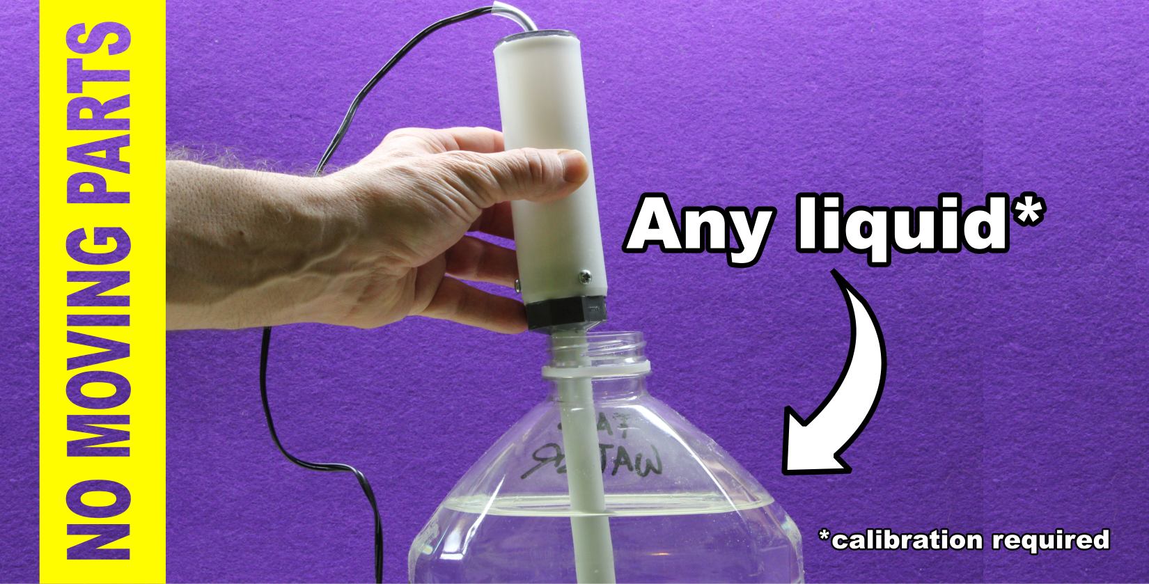
Unlike other sensors that are based on a float, capacitive sensors have no moving parts, so they are very reliable. Even conductive sensors have no moving parts but they are sensitive to corrosion and current leakages in the case other electric devices are in contact with the water, for example a pump. Ultrasound based sensors are another example of sensors that don't have moving parts, but they are expensive while cheaper ultrasound emitter-receivers are sensitive to moisture, splashes, and vibrations.
A multi purpose sensor
The sensor I've made is useful wherever the level of water or other liquid (i.e. cutting fluid) have to be monitored and controlled such as in hydroponics, in watering systems, machine tools, food processing machineries, sumps, and so on.
How capacitive sensors work?
Capacitive sensors work by exploiting the variation of the dielectric coefficient when the two sensor's plates are plunged into a fluid, where those two plates constitute a capacitor.
So the sensor is basically made of two plates that are connected to a conditioning circuit which measures the capacitance.
Admittance Vs. Capacitive sensors
Admittance sensors also exploit the capacitance between two plates but in place of measuring the capacitance they
measure the admittance, which is the opposite of the impedance.
So they are pretty similar to capacitive sensors, the only difference is in the circuit that instead of
measuring the capacitance, sends a fixed frequency alternating signal and then detects the variation of impedance.
Being the impedance of a capacitor given by its capacitance at a given frequency, changing the capacitance (by varying the
dielectric coefficient) the impedance also changes.
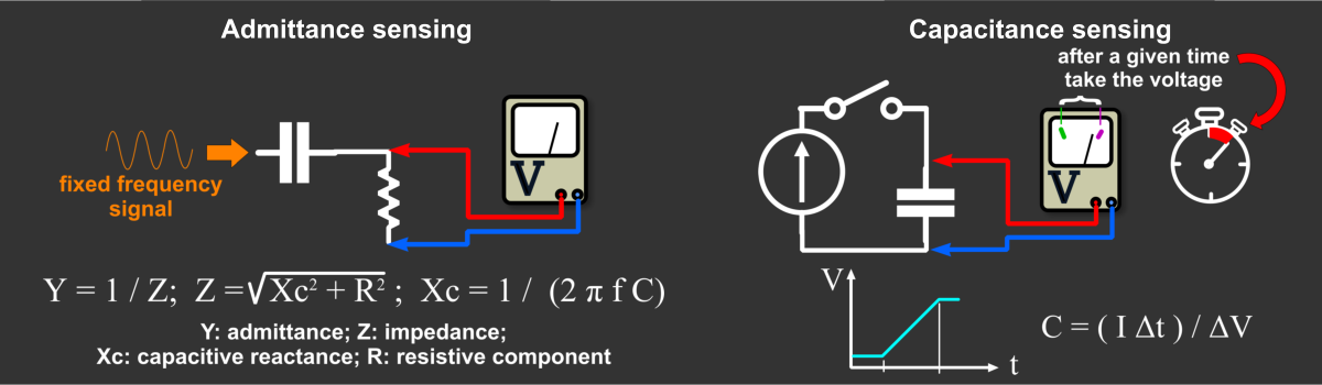
Capacitive measurement: voltage Vs. frequency
The above drawing shows one method to measure a capacitance, which is to look at the variation of voltage that build up
across the plates of the capacitor while charging it with a constant source of current, within a fixed frame of time.
But another method do also exist.
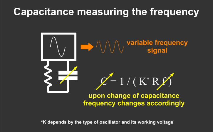
Inserting the capacitor to be measured into a resonant circuit, the frequency of such a circuit would change accordingly
with the variation of the capacitance.
This is the circuit I choose for my sensor.
Why? It is simple, it can be quickly built around almost a single integrated circuit, and it is dirty cheap to make.
Also the signal can be easily converted into a proportional voltage that in turn may be used to drive the input of an
analog to digital converter of a microcontroller such as Arduino or an ESP8266.
How the sensor is made
The sensor is made of two elements: the detection and conditioning circuit, and the probe. The two elements are attached together in a single unit.
Making the probe
Two stripes of aluminum are used in order to make the plates of a capacitor that will be located into a plastic pipe.
Because the stripes must be isolated in respect to the fluid, which may be conductive, I have covered the stripes with a
layer of bi-component polyester resin and on top of it a further layer of acrylic.
About five centimeters at one end of each stripe have not been covered with the insulating resins as that segment will be the
terminal contact.
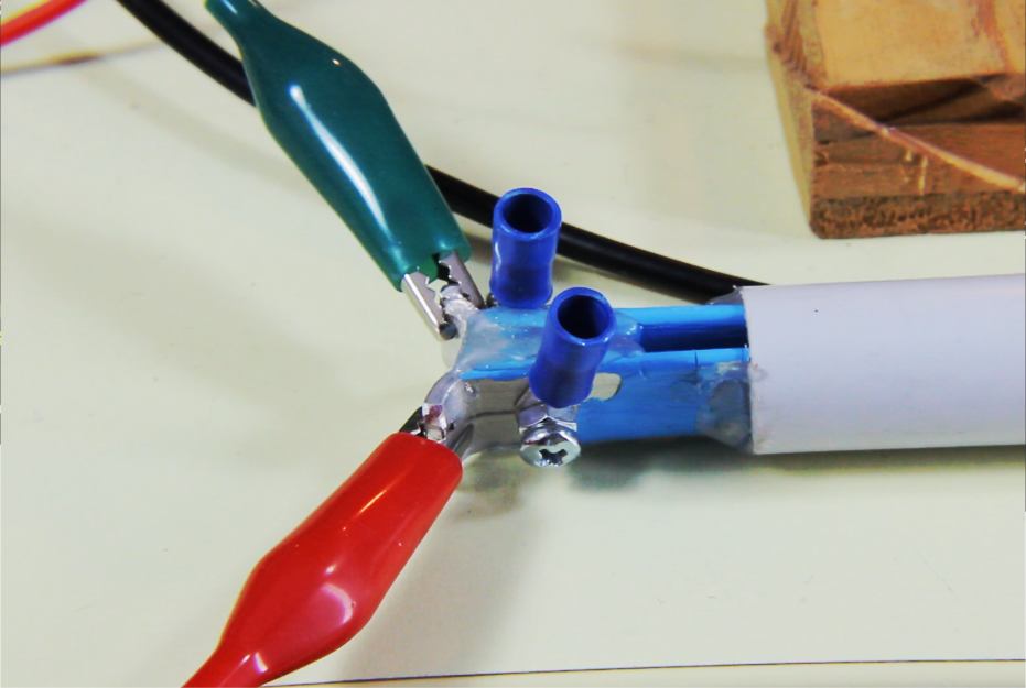
Then the stripes have been placed into a PVC electrical conduit and kept in place using hot glue. To be sure to have the right gap between the two stripes I've temporarily put a dense sponge in between. This sponge will be extracted once the glue is set.
A better design (see Fig. B) would have been to use an aluminium pipe, also connected to ground, and a inner rod to form the other plate of a coaxial capacitor. The external aluminium plate would work as shield from induced electric fields making the oscillation more stable. Following you will see the first iteration where I used the design shown in Fig. A.
While at first I thought to make this sensor also with the idea to gauge the level of sewage water accumulated into a sump pit, ultimately I discarded the idea as the gap is too narrow and it could easily be clogged by the sludge. An alternative probe will be made in the future to cover this application too.
Determination of the capacitance
First we need to figure out the theoretical capacitance of the sensor in both fully immersed in water and when in dry status.
The capacitance can be calculated by dividing the area of one of the two stripes (representing the plates of the capacitor) over the distance of the stripes. This ratio is then multiplied by the permeability (or dielectric constant) in vacuum, and by the relative dielectric constant of the resin, approximately 3, which covers the plates. Even though between the plates there is air too, we do not need to multiply also by the dielectric constant of air because it's close to 1.
This gives us a capacitance of approx. 29 pF when the sensor is dry.
Calculating the capacitance when the sensor is fully immersed in water is straighforward: just use the length of the stripe that will be immersed to calculate that area, divide by the same gap distance, and multiply by the same dielectric constants as when the sensor is dry, and by the dielectric constant of water, which is approximately 80. A pretty sharp difference in respect to the air!
This gives us a capacitance of approx. 2.4 nF.
If in place of water we have another fluid, let's say oil, we need to use that permeability value instead. Also keep in mind that permeability may change with temperature.
To be precise the remaining part of the sensor that remains not immersed should be calculated as we did in the dry status, and added to the just calculated capacitance of the part that is immersed. However since the remaining part is very small and the difference between the air and water dielectric constant is so large, we can safely disregard this part.
Detection and conditioning circuit
The detection circuit is made around a single integrated circuit, a 74HC132 four logic NAND gate with Schmitt trigger inputs.
This component is critical and should not be changed.
The first gate with the 150KΩ, and the 22pF in parallel with the probe form the resonating oscillator.
Then it follows the conditioning circuit that is made of a pulse generator, which is comprised by the 82Ω and 10nF
in series, with the 1N4148 diode and 560Ω reistor connected to the input of another gate.
The pulse generator with the following gate and the two 2.7KΩ resistors and the 100nF capacitor together form the
frequency to voltage converter.
So the oscillator detects the resonant frequency of the 150KΩ resistor with the probe capacitance (the 22pF capacitor provides a fixed floor for the oscillator). This frequency is then converted into a voltage, that can be used to know at which level the probe has been immersed into the fluid.
It is important to note that the length of the pulses are meant to be shorter of the shortest cycle of the oscillator when the probe is completely dry, namely when the capacitance is at its lowest value and hence the frequency is at its maximum.
The final comparator made around a LM311 provides a signal when the voltage trespass a given level. It can be used as an alarm, as I did with the buzzer and the LED connected at its output at pin 7. The LM311 is an open collector comparator so when the threshold set by the 10KΩ potentiometer is trespassed the pin 7 is closed with pin 1, which is connected to GND.
Video
Watch the video to see how it works and how it was made.

Don't miss next post
Subscribe to stay up to date when new articles, videos or other contents are available.
RELATED ARTICLES
RECENT ARTICLES
 Subscribe
![[Valid Atom 1.0]](../valid-atom.png "Validate my Atom 1.0 feed")