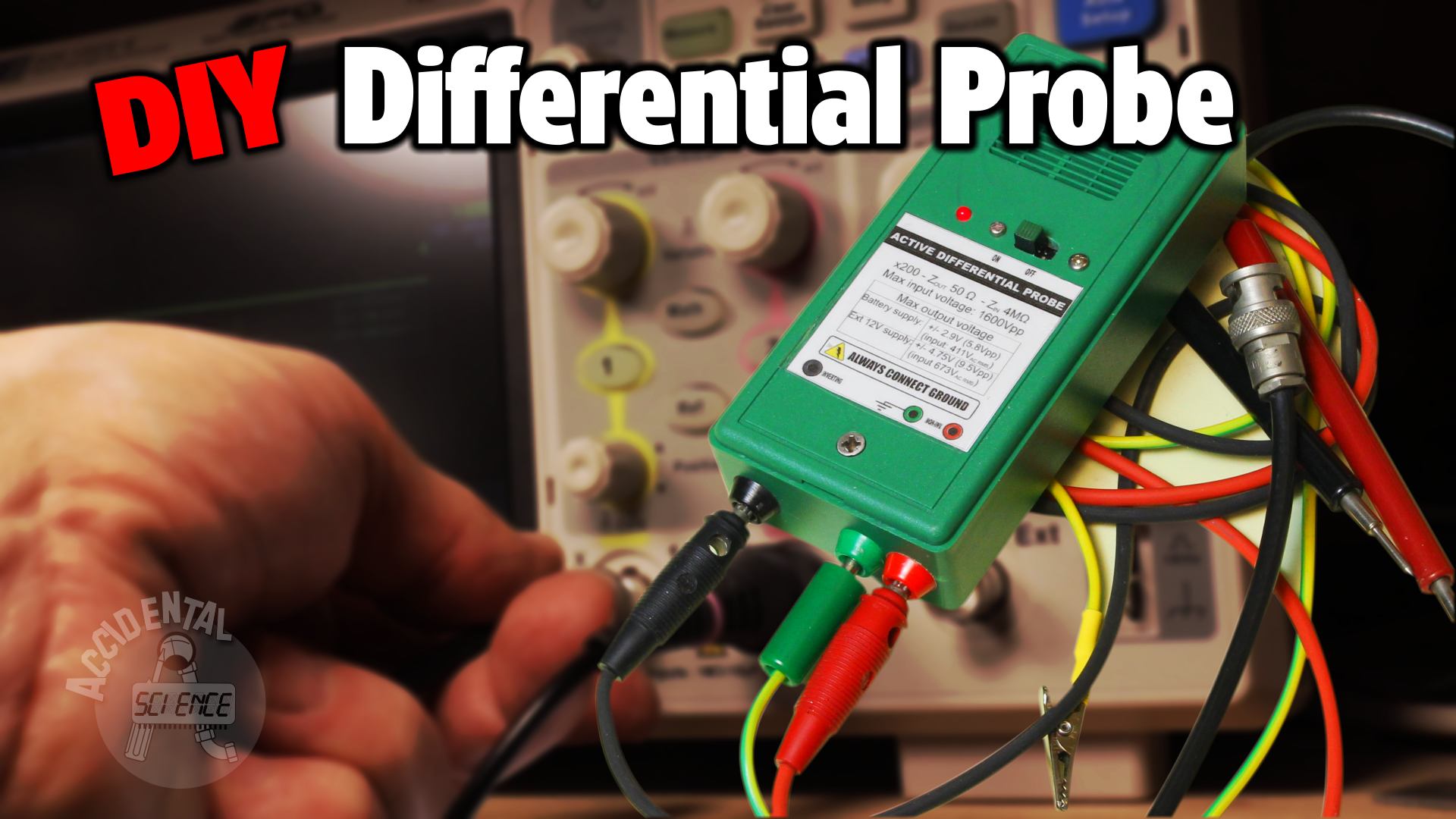
DIY differential probe

CAUTION: Working on mains voltage is dangerous, you MUST know what you do.
Directly using the probes of the oscilloscope to measure the mains is hazardous, as it could lead to from destroying your
probes to melting the traces of the PCB inside your oscilloscope, not to mention the risk of being injured. Depending on
the grid system, you may have 50% to 100% chance of causing a short that may destroy your instrumentation.
Simple and dirty cheap
In a previous article I presented a depth analysis of why you can blow up your oscilloscope while making measurements at
mains, so I recommend you to read that article if you are unaware of the risk involved.
Often people think that the trick that uses two attenuated probes could be a safe way to measure waveforms on the mains,
however it may end up in catastrophic results if you work on voltages above 110V RMS.
The solution I present here in this first part of the article is a simple attenuator made of just 1/4W resistors, that guarantees safe operations with the oscilloscope provided the PE (Protective Earth, the yellow-green/green wire) is actually tied to ground. It still requires two input channels of your oscilloscope but it is safer than directly hooking the probes to the mains, in particular if you're measuring voltages that are at 220-240 volt RMS.
Please watch the video for details on how and why I made it in the way it's made:

DIY Active Differential probe
In this second part of the article we'll see how a simple and cheap active differential probe can be home made.
This is an active differential probe designed for the measurement and visualization of waveforms of mains voltage (or at mains' voltage level) on a common oscilloscope without running the risk of frying the scope, the probe, or worst yourself!

Unlike the passive probe shocased in the previous section, this active probe uses only one input channel of the oscilloscope providing a significative advantage. Also, because the probe is tied to GND you can use the second channel to make measurements on other circuits that are referenced to ground without running the risk of interference or of damage.
The probe run on a 9V battery that lasts about 20 hours (based on Duracell's data sheet calculated for the current drawn by the circuit.) It features an input impedance greater than 4 MΩ, an output impedance of ~50 Ω and an attenuation ratio of x200 (200:1). The theoretical maximum input voltage is 800Vp (given by the voltage limit of the resistors used in the attenuator). This allows to take measurements not only on common 230/240Vrms but even at 380/400Vrms (used in Europe), including phase-to-phase on a three phases system.
BEWARE that if you try to make this project yourself you'll do it under your own sole responsibility, I'll take no liabilities! Keep in mind that the circuit's performance and limits heavily depends by the components used and how the circuit has been made. I mounted two of the four resistors of the attenuator on the PCB and has been covered with an insulating resin that is NOT visible in the pictures.

The probe is built around an LM4562 in an Instrumentation Amplifier configuration, and a resistive attenuator. Tests confirmed that there is no need for capacitive compensation since the input capacitance is remarkably low (less than 2pF) and the frequency range of interest is about mains frequency (50/60Hz) and its harmonics, so rarely there is the need to read frequencies above 20Khz. I hadn't the possibility to test the probe for its actual bandwidth, though.
For the sake of simplicity I used common 1% resistors (with 20ppm/C) rated 250V. The "high" voltage must be well separated by the low voltage part. The key point of this probe is the link to ground, or PE (Protective Earth) that provides its safety. So it is important that the PE is connected while in use! It works on both TT and TN systems. The PE is also carried by the oscilloscope, but the provision of a separate connection for grounding (the green banana socket) is important in the case of fault of the cable, the use of a battery powered oscilloscope and the case when the plug is disconnected from the scope.
This probe MUST NOT be used where the line is not protected by a GFCI, RCD or RCCB.
How it works
With reference to the schematic below, the circuit is made of a dual branch attenuator (on the left side) that is connected to the
differential inputs of an Instrumentation Amplifier composed by the two OpAmp located inside a single package LM4562.
In the schematic, the upper OpAmp works as a non-inverting buffer having gain = 2, its output is carried to the lower OpAmp
into the inverting input which, in this case, has a gain = 1. The non-inverting input of this latter OpAmp follows the voltage
coming from the second branch of the attenuator (the inverting input). The attenuation with the gain makes a total attenuation of
200 times (46 dB).
The output of the last OpAmp is adapted for a cable impedance of 50 Ω.

The last OpAmp, an OP07 (but I've also tested a LM741 with no noticeable difference) is used to provide a balanced power supply to the LM4562 from a single 9V battery, by which the probe operates.
Video
Watch the video for more details, theoretical explanation and tests:

Don't miss next post
Subscribe to stay up to date when new articles, videos or other contents are available.
RELATED ARTICLES
RECENT ARTICLES


 Subscribe
![Validate my Atom 1.0 feed [Valid Atom 1.0]](../valid-atom.png)