Buck Converter

In this article:
- What is a buck converter and why you'd like one.
- How it works in simple terms.
- Pros and cons and how to avoid common pitfalls.
What is a buck converter
Every circuit, every device need a specific voltage to work properly. However sources of electric power not always, if ever provide the correct voltage for a given device. To adderess this problem typically a voltage regulator is used, and the most commonly used one is the linear voltage regulator. This kind of regulator chokes the output voltage by making it to drop at a transistor that works as a variable resistor controlled by a feedback circuit (see conceptual diagram).

Linear voltage regulators such as the LM7812 provide good noise rejection and stable voltage. Though they are not much
efficient, in particular when the difference between the input and output voltage is large and some high current must go
through the regulator.
The following table gives an idea:
Voltage drop
Current
Power lost
3V
0.1A
0.3W
3V
1A
3W
10V
0.1A
3W
10V
1A
10W
As you can see as the current or voltage drop raises the power losses increase quite significantly.
Switching is the key word
Because to make the output voltage stable linear regulators work by linearly dropping voltage across them, they unavoidably have low efficiency. The key here is the linear relationship between the output voltage and the voltage drop across the regulator, so what if we break this linear relationship?
Well, this can be achieved by switching on and off continuosly and making some kind of average at the output. This is in
essence a buck converter: it chops the input power into a smaller output voltage, and related current.
This is an interesting feature because on linear regulators the input current is the same as the output current, while
with the buck converter this fixed relationship is broken and we can get more current at the output than the one that
flows at the input, provided the overall power is the same.
More precisely the output power must be less than the input power to account for the losses introduced by the process
of conversion.
How a buck converter works

Referring to the picture above, we have two phases: On-state and Off-state. While in on-state the current is pumped into
the inductor to charge the capacitor (see the red lines). In this phase the energy is stored into both the inductor and
the capacitor, and also going through the load.
When enough energy is stored and the output voltage reaches the desired level, it switches into the off-state.
The switch opens (in a real circuit the switch will be replaced with a voltage controllable switch such as a MOSFET) so
the sudden change in current across the inductor would make it to accumulate charges at its terminals creating a voltage.
That would keep the current to flow if a path for the charges is found to reach the other terminal of the inductor. This
is achieved across the diode, so the current can flow from the inductor, through the load and back to the inductor up to
the point the stored energy is dissipated. At this point the cycle starts over again.
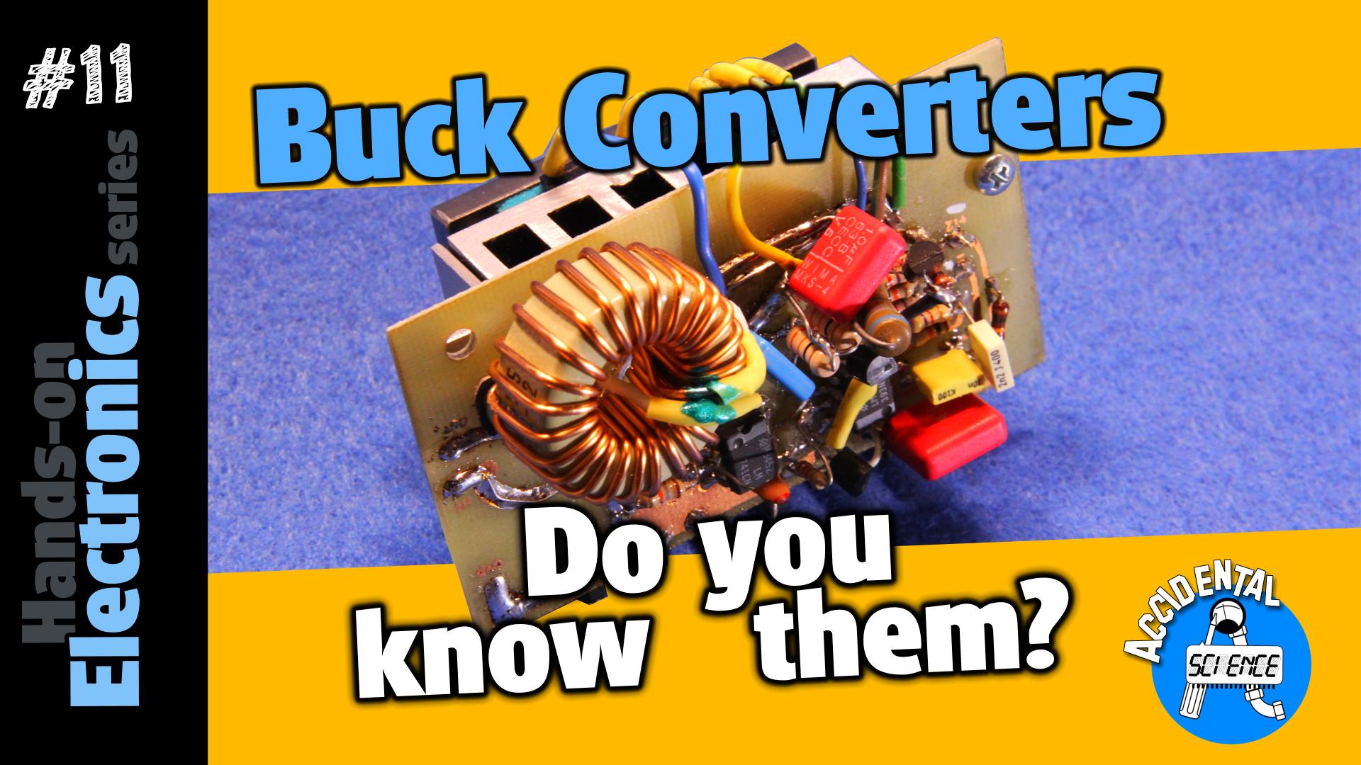
My own Buck Converter

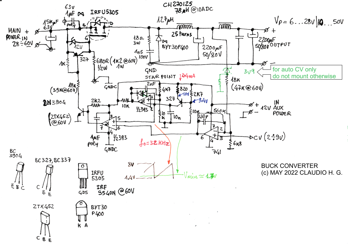
The above schematic shows the buck converter I've designed and built. You can spot the main switch as the IRFU5305, the
main diode as the BYT30P400, the main inductor is a 78 μH, the output capacitor is the 2200 μF. The other inductor
and capacitor are used to filter out the switching spikes. It is important to note that the first capacitor (the one
connected with the main inductor) must be a low ESR cap to reduce noise and to make the circuit more efficient.
Also about the diode a better choice would have been to use a schottky diode, but I didn't have any suitable diode at the
time of the build so I used a silicon fast recovery switching diode, and to help the transition between the conduction
states a snubber has been added. It is composed by the 18 Ω 3W carbon resistor and the 1.5nF 100V polyester low ESR
capacitor. to avoid the risk of spurious ringing the chosen resistor must have a very low parasite inductance.
The remainder of the circuit is to just drive these main components. The 741 Op Amp is used as an error amplifier to
compare the output voltage in respect to the control voltage (CV). Its output goes to one of the two comparators that
fit a LM393 dual comparator. This error voltage is compared against a sawtooth waveform generated by the other
comparator and the BC327 transistor configured as a constant current source that charges linearly the 10nF capacitor
generating the rising ramp. Since the comparator sports an open collector output this is also used to quickly discharge
the capacitor, completing the sawtooth waveform.
This sawtooth is then fed into the first comparator to generate a PWM signal that controls how long the MOSFET should
stay at on-state.
Notice that, to increase efficiency by speeding up the time the MOSFET takes to turn off, the driving circuit is configured so that the MOSFET is normally ON when no driving signal is issued to the first 2N3904 transistor (or ZTX452 if the circuit works at 60V), because the MOSFET is normally kept to GND through R 680 Ω.

Features
- Input voltage: 28V or 60V DC
- Output voltage: 6 to 28V or 10 to 60V DC
- Max current: 10A
- Efficiency: 93%
- Switching frequency: 32KHz
Pros and Cons
Now its time to have a look at what are the pros and cons of a buck converter in place of a linear regulator. First off
we can notice that the buck converter works by swicthing the current through different paths. This means we may have a lot
of noise emitted from these different paths. Thus one important point when designing a buck converter is the layout of
the components and to pay attention at the path the current will follow. Reducing the distance between these two paths,
and in particular to avoid the GND bouncing, it is of paramount importance to limit the noise both radiated and induced. So buck converters may be hard when dealing with EMI, or passing an electromagnetic compatibility test. Clearly linear
regulators do not suffer from this kind of problem.
Of course swicthing circuits have bulkier and more expensive components, such as inductors and low ESR capacitors.
So we can summarise the pros and cons as follow:
Buck converter
Linear regulator
Pros
- High efficiency
- Constant output power
- Low noise
- Less components and less expensive
Cons
- Bulkier and more expensive
- Noiser, requires filters and careful design & testing
- Low efficiency
- Output power decreases with output voltage
More information and how to avoid common pitfalls
Watch the video to get more information, waveforms, a theoretica explanation and how to avoid common pitfalls.

Don't miss next post
Subscribe to stay up to date when new articles, videos or other contents are available.
RELATED ARTICLES
RECENT ARTICLES


 Subscribe
![Validate my Atom 1.0 feed [Valid Atom 1.0]](../valid-atom.png)