

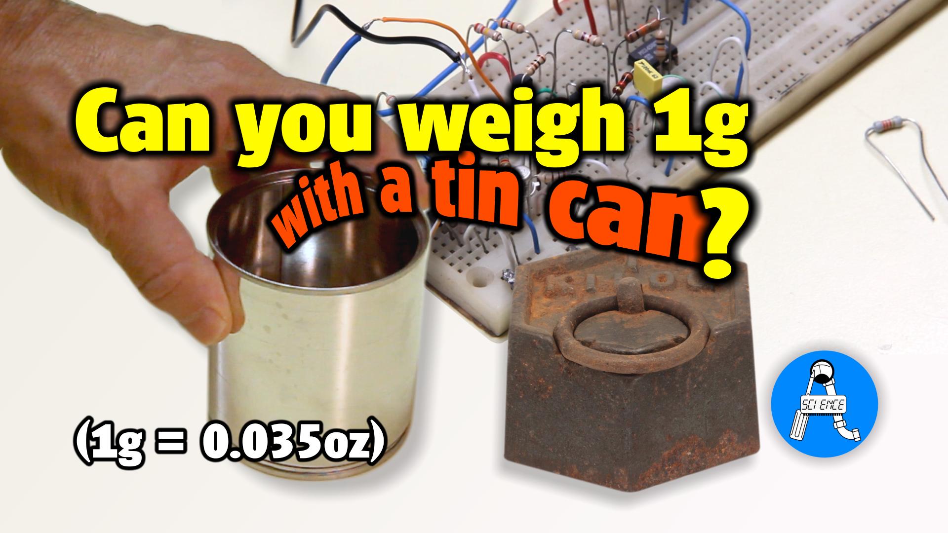
How to make a capacitive scale

This project is just for fun and as an educational experiment to show capacitive sensing.
While this project is a simple educational/for fun experiment, actual sensors exploit this very same technique to gauge pressure or weight. Of course commercial products do not use a tin can! 😊
So everything you have to know is that through a simple tin can you can make a scale able to weigh small masses as low as one gram (0.035 oz).
Working principle
The working principle is based on stiffness and the electric capacitance, exploiting the elastic deformation of the bottom of a can. Tin cans usually have the bottom that is corrugated to accommodate possible expansions or contractions of the contained food and the air trapped into the can, behaving like a spring. And we know from the Hooke's law that a spring expands or contracts proportionally to the force exerted. Of course, in our case the force is provided by the Earth's gravitational force.

The second part is about capacitance. We know that the capacitance is inversely proportional to the distance between two
plates that face each other. So if we have two plates that can move proportionally to the weight of the mass we want to
gauge we have realized a scale.
The spring effect from the concentric, corrugated bottom of the tin can will effectively counteract the force exerted by
the mass that is given by the attraction caused by Earth's gravitational acceleration:
f = m a = mass × 9.81 m/s2 .
How to make it, practically
So to exploit this spring effect and put everything together, we will use the concentric corrugated bottom of a can as a
first plate, and a flat disc (also reclaimed from the same can) as a second plate.
This last plate will be glued on top of a plastic box that provides a structural base for our makeshift scale.
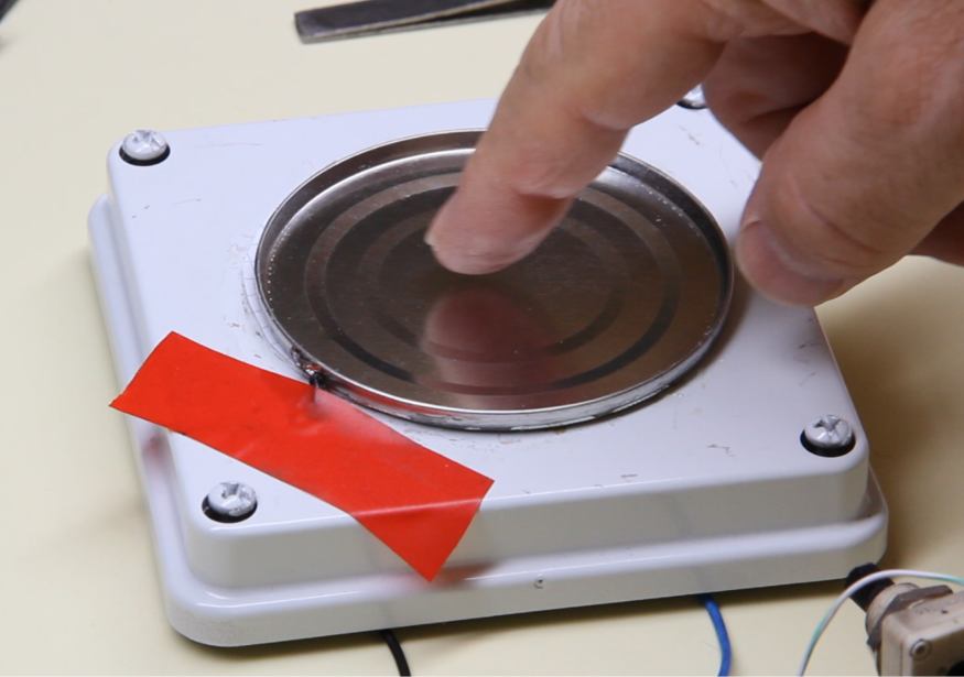
On top of it we put the first plate (the bottom of the can) in a way that its rim lays on the rim of the lower plate. A sheet of paper is placed in between to prevent short circuit. If the rim has not enough relief we can add a ring of paper to increase the distance between the two plates.
How it works
Because the corrugated plate is slightly distanced at the center, placing any object on it will make the plate to deflect a tad toward the lower plate, reducing the distance between the two plates. The amount of deflection is proportional to the force exerted by the weight of the object, that in turn is contrasted by the spring force of the top, corrugated plate.
The two plates are separated by a small air gap. These two spaced and isolated plates form a capacitor. So combining the proportionality of the force with the deformation, thus the distance between the two plates, and the capacitive effect, I've created a capacitor that varies proportionally to the applied force.
Now the trick is how to grab this tiny variation of capacitance, which is in the range of 110 to 60 picofarad.
Electronic circuit
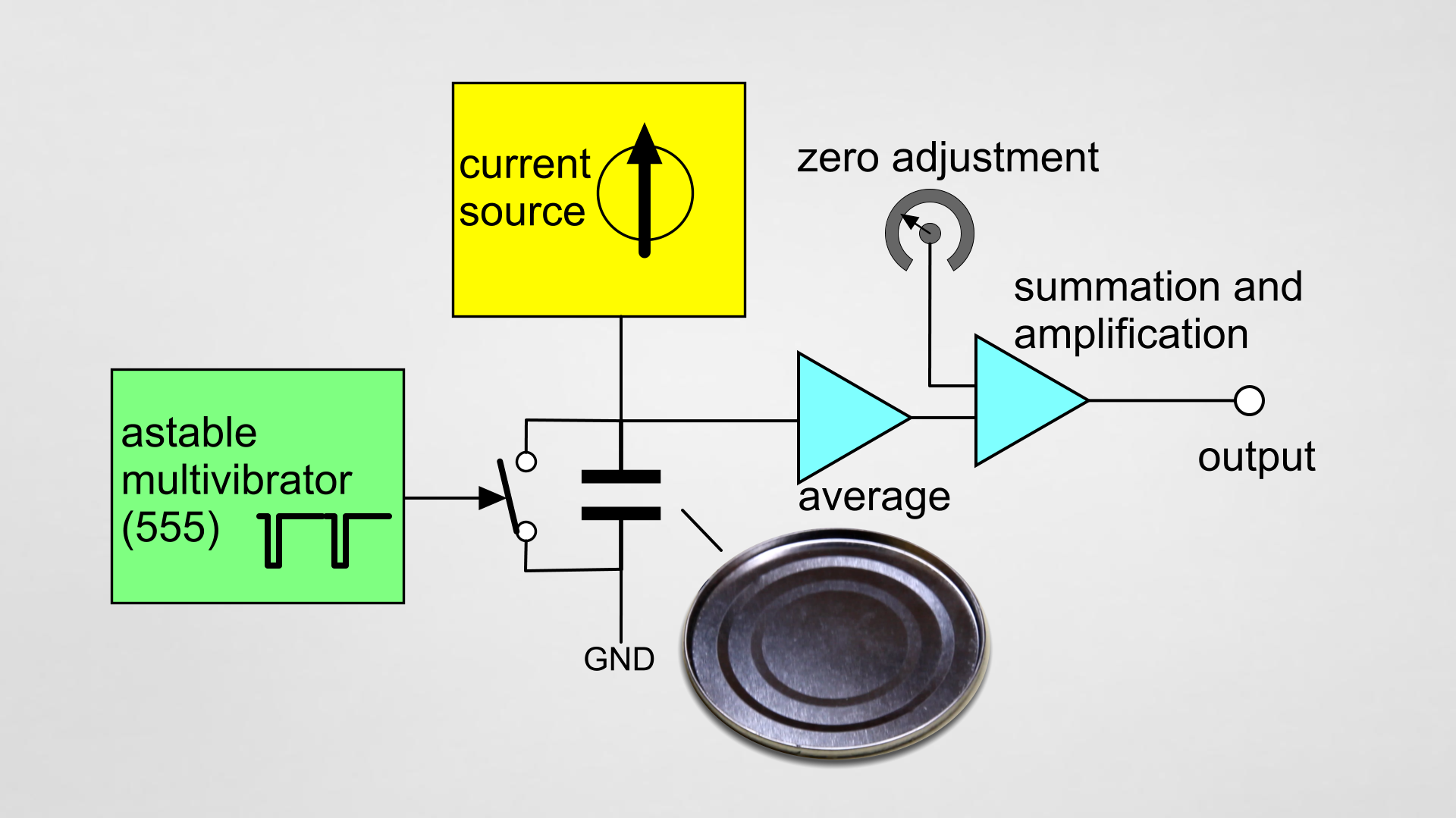
The circuit I've designed provides a current source to drive our special capacitor (C sense), the weigh sensor, that is periodically shorted by a transistor driven by an astable oscillator made around of a 555. Because the interval generated by the 555 (IC1) is constant, the voltage that will build up across C sense will be proportional to its capacitance. Then this voltage is averaged, amplified and summed with an offset to get at the output a voltage spanning from zero to four volt when full force is applied.
The "zero adj." potentiometer adjusts the zero point.
Because the plates may pick up some environmental noise, and in particular mains noise, to curb this a filter has been added and an accettable final ripple is around 1.25%.
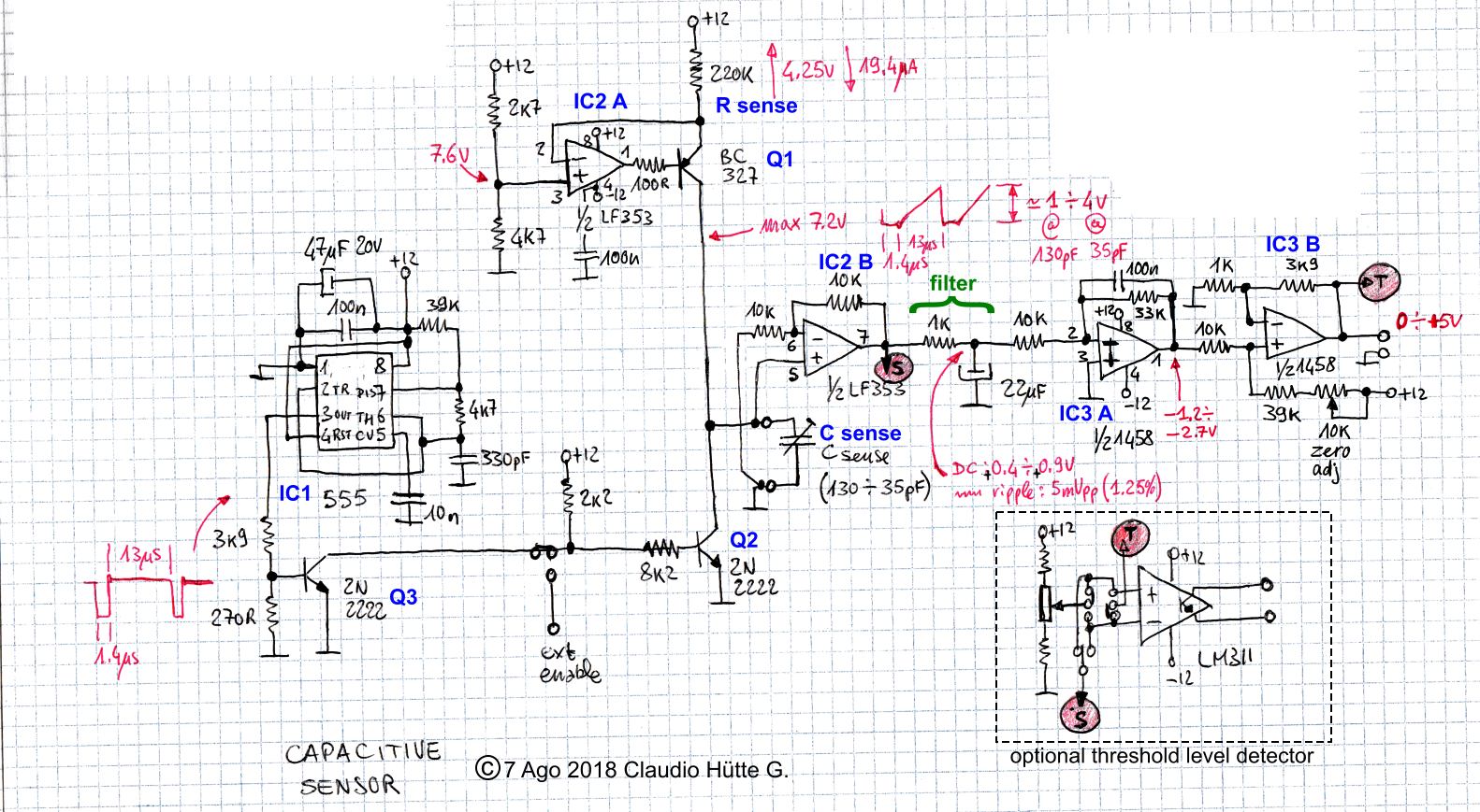
Current source
This is made around IC2 A and Q1: IC2 A will try to keep the voltage across R sense constant, thus the current that flow across it and Q1. This will cause the capacitor to charge linearly over the time.
Time interval generator
The IC1 provides a fixed interval where Q2 stays Off for 13.5 μs and On for 1.4 μs. This allows a fixed time of 13.5 μs to charge. Because the voltage at the capacitor is given by: V = (I t) / C ; since t is constant (at 13.5 μs) and I is constant (at 19.4 μA) the voltage will be proportional to the capacitance C.
Buffer
We need to decouple the sensing capacitor with the remainder of the circuit to avoid to divert current from the capacitor.
So the other half of IC2 (B), a JFET input Op Amp type LF353 is used to work as a buffer.
Amplifier
The signal needs to be filtered and amplified. For this purpose a R-C is inserted as a filter, and IC3, a dual LM1458 Op Amp provides for the required amplification. Also a potentiometer is inserted in the circuit to offsets the zero point.
An optional comparator (see LM311) can be further used to make a threshold detector.
Results
- With a screw which is 1 gram we have just a tiny variation of 0.02v. This will be used as a reference to convert voltage to grams.
- The tweezer weight 22 grams that produces about 0.4V, so 0.4V/0.02v/g = 20g
- The screwdriver which is about 16 grams gives approximately 0.3V, so 0.3V/0.02v/g = 15g
Remarks
When I've shown the working demonstration I've got some reading also placing a screwdriver that laid on the edges of the top plate (the can's bottom). This would be unexpected because the corrugation gives elasticity from the center of the plate, but I've read something close to a real measure because this is a makeshift arrangement where the paper and some irregularities of the bottom plate makes the top plate to work even in reverse, that is making the edges coming toward the bottom plate instead of the center.
Video
Watch the video with the full demonstration of the experiment:
Don't miss next post
Subscribe to stay up to date when new articles, videos or other contents are available.
RELATED ARTICLES
RECENT ARTICLES
 Subscribe
![[Valid Atom 1.0]](../valid-atom.png "Validate my Atom 1.0 feed")