

Intervalometer-Trigger-Stop motion and Dolly controller - Part 2
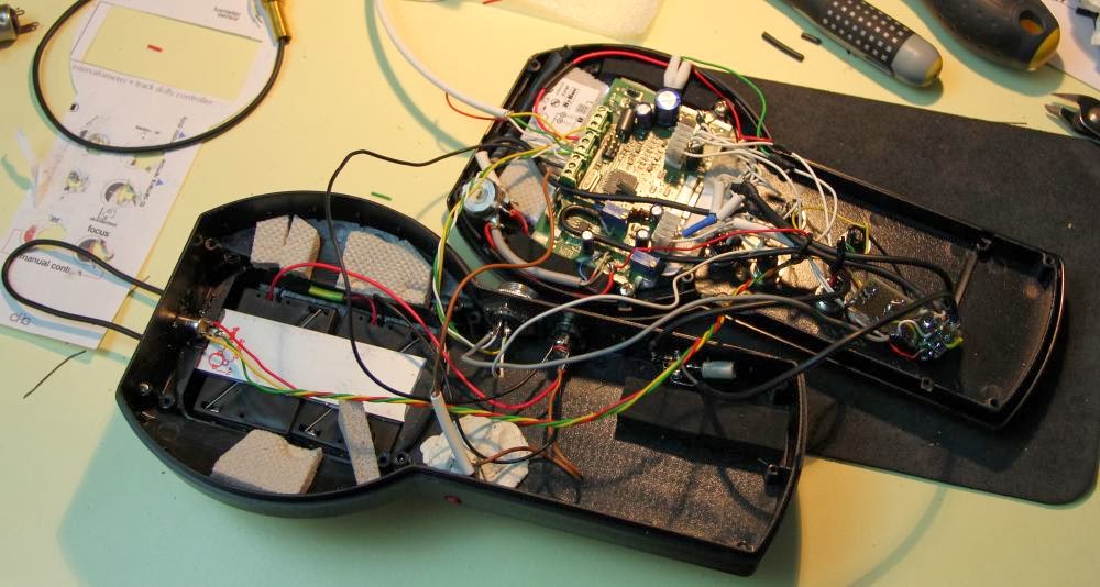
In the previous post I have given an overview of the Intervalometer, Trigger, Stop Motion and Dolly Controller, describing the characteristics and functions. Now it's time to dig deeper into the unit, opening the enclosure and look at the internal circuits.
New functionalities
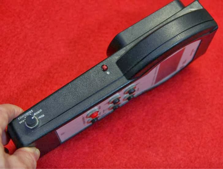
Because I added functions step-by-step while experimenting results, I made some small circuit boards to expand the basic circuit to include the new functions. So, for example, when I tested the trigger with an external microphone I discovered that more sensitivity to catch not only loud sounds would be nice to have. So the circuit now can also pick weak sound events such as a falling drop of water hitting the surface. Of course this required to add also something to adjust such a higher sensitivity, so I added a potentiomenter that is visible in the final design (see pictures).
Schematic - The Analog section
The final circuit is shown below. The first schematic is the analog section, which essentially is a preamplifier, with a total AC gain of 74dB, a photoresistor sensor is connected to a JFET Op-Amp LF351. This decouple the photoresistor (and the related resistive network) from the external trigger input connector. This one is biased via a 3.9 KOhm from the +5V rail to provide the plug-in power for an electret microphone. The 22µF capacitor decouples the DC component, so we will be more sensitive to transients.
The LF351 it is not designed to work at low voltage, however, I found that it works if the input voltage swing is limited in range. Maybe another OpAmp would have been a better choice, but that was what I had in my drawer, and after all the LF351 do its job with more than acceptable results.
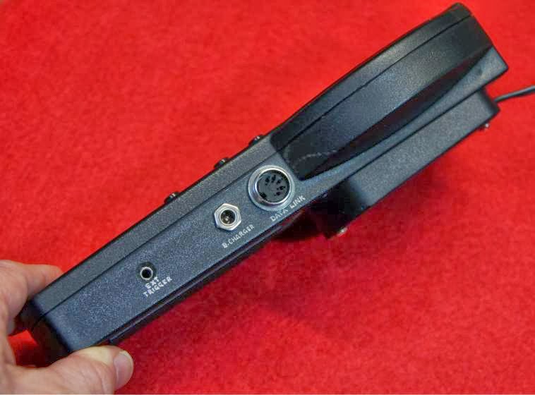
Other components are the two 18KΩ resistors to provide the battery level to the microcontroller, and three optocouplers 4N35 (or any equivalent) to drive the remote control input of the camera. Canon cameras, besides many others, have a simple way to remotely control the camera: pulling to GND (or the ring, referring to a 3.5mm TSR jack plug) one terminal releases the shutter, and the other terminal drives the auto focus. Also, Canon's shutter terminal is connected to the tip, and the focus terminal is connected to the sleeve of the jack plug.
Optocoupling is the best way to keep things separate, avoiding the risk of currents leaking from one circuit to the other.

The grayed section on the top right in the above schematic is an optional additional OpAmp meant for fast triggering. Since trigger is controlled by comparing the analog signal with a digital threshold, the response time is limited to about 2 milliseconds. This OpAmp should be a comparator (such as the LM393) that detects when the input analog signal trespass the threshold adjusted by a potentiometer or, in a simpler solution, by an internal trimmer, so the main sensitivity potentiometer would indirectly also adjust the level at the comparator as well. This changes the level seen by the IN2 input of the controller. Those inputs are scanned in about 100 microseconds, so it is really faster than the analog detection. Notice that I forgot to add a pull-up resistor at the output of the OpAmp comparator, if you want to build this circuit you need to add this resistor (say 2 to 4KΩ) connected to +VBatt.
Schematic - The Digital section

The second schematic is the digital section, with the microcontroller-display LCDG (I will talk about this device in a future post) hackered to pick up the +5V, directly connect the AN0 analog signal, and to reduce the voltage drop caused by input diodes. Finally, a jumper is soldered to connect an additional diode (already installed on the PCB) to short the input power supply if it is reversed in polarity. This works in combination with the external fuse visible between the two 3x battery compartments. To complete the circuit a connector with four buttons is connected to the 8 pin head (aligned on the left, the last 6,7 and 8 pins must not be connected), and wiring to the DIN 5 poles connector for data exchange, JC1 and JP3 connectors to the analog circuit seen above.
Once connected it is time to program, but I will discuss this topic in a further post.
Photo gallery


Don't miss next post
Subscribe to stay up to date when new articles, videos or other contents are available.
RELATED ARTICLES
RECENT ARTICLES
 Subscribe
![[Valid Atom 1.0]](../valid-atom.png "Validate my Atom 1.0 feed")