

The Ultimate Power Supply
Ever dreamed for a compact power supply that provides all the voltage source you need? If so this is the project for you!
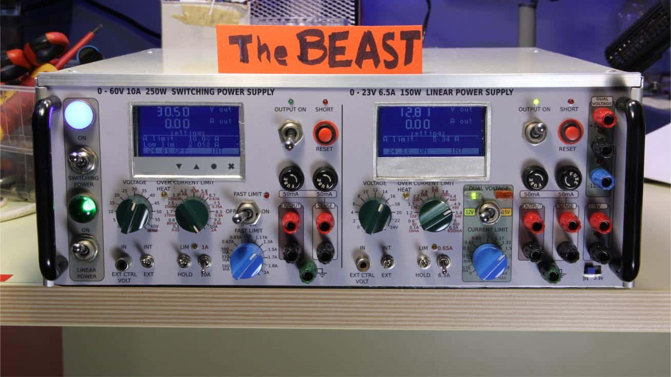
This is the Ultimate Power Supply for your lab. It appears a bit crude, but quite functional.
Here are the main characteristics
Three isolated units: 0-60V; 0-24; ±12/15V & 3.3/5V (with common).
This means that the units can be wired as desired and are unrelated among each other, making it possible to feed different circuits with unrelated common, or wire the units in series to increase the voltage and have tapped points.
Unit
Voltage range
Max current
Power
60V
Adjustable:
0 - 60V
(w/external control)
10A nom.
4A @ 60V
10A up to 25V
300W*
24V
Adjustable:
0 - 24V
(w/external control)
6.5A
156W
±12/15.
3.3/5V.
fixed selectable:
12V or 15V
+ 3.3V or 5V
1.5A
75W
*The is limited by the used transformer, the circuit could provide 10A at 60V if a transformer larger than 600W is used.
External control

The variable power supply units can be optionally controlled externally with a voltage from zero to 5V.
The input for external control voltage is isolated in respect with any other part of the power supply so it is possible
to have the output of the power supply unlinked with the source that provides the control voltage.
Swicthing regulator - Excludable
The 60V / 10A unit is provided through a buck converter for high efficiency, which in this case is 83%. Even though it has been well filtered, the buck converter can be a source of noise, in particular when testing sensitive circuits. So this section che be switched off separatedly from the other linear units.
Current limiter
All the units have adjustable current limiters. Because the main current regulator for the buck converter can be a bit slow in response, I also added a supplementary current limiter that is normally bypassed. This limiter is much faster and specifically calibrated to react for smaller current (max 2A).

While the current limiter for the adjustable 0-24V unit is of great precision, the current limiters for the fixed selectable
units has low precision and it is primarily meant as a rough protection against overcurrent when testing a circuit for the first time.
Also this last limiter is unable to bring the current down completely as the output cannot go below approximately 2V.
How it works
Following is given a functional diagram of the whole system. Each unit could be considered as an indipendent block, which is coumpounded into a single enclosure.

You can notice that each unit uses an independent transformer. However for the 24V I used two transformers, for a grand total
of six transformers. I chose this option because I already had these transformers and in this way I increased the power to reach
a total of 300VA, connecting them in series. Each one provides 10-10V, so I wired them to obtain 30V AC.
Also to reduce the power dissipation a couple of relais have been used to switch between 20 and 30V AC based upon the required
output voltage as set with the potentiomenter or through the external voltage control. (See schematic below.)
The microcontroller read this voltage request and switches the two relais accordingly.


Fixed Selectable Voltages PSU
Following schematic is about the last unit that provides the fixed selectable voltages. This is powered through an independent
transformer, as the previous ones, but in this case I used a toroidal transformer that already cames with two 15V secondary coils.
On this I added a third coil to obtain 7V AC to feed the 3.3 / 5V regulator.
Here you can see a video I made
about how to add coils to an existing toroidal transformer.

For more details about this power supply please give a look at this page: Fixed Selectable Voltages PSU.
0 - 24V 6.5A Linear Power Supply
Voltage control.
The core of the circuit is about OP AMP U4A which is the main voltage loop that controls the output voltage. It takes the reference
voltage given from the potentiomenter RV1 or from the isolated input. The isulation is provided by U5A and the two optoisolators.
That section of the circuit is fed through a separated transformer and regulator to make sure it is galvanically isolated.
The voltage loop regulation is completed by U6B which read the output voltage either directly from the output sockets or from a sense point. R4 and R8extra provides automatic feedback if sense inputs are not used.
Power Section
The output of U4A controls the main power transistor QP, which is in Sziklay configuration with Q2, which in turn is driven by Q1.
This last transistor must withstand a certain amount of power given by the maximum output voltage plus QP VBE and the current
necessary to drive Q2. This is also designed to minimize the power dissipated by R1.
Notice the indicated transistor is a power darlington that should be used if the input voltage is raised at 45V DC (unloaded, or
from 33V AC nominal) and current up to 10A. If the voltage is at about 41V DC (unloaded, or 30V AC nominal) and current is limited
to maximum 7A a BUX40 or BUX41 or BUV19 can be used. These transistors have very low thermal resistance case to heat sink, but have
less surface contact of the internal chip so their SOA is a bit worse.

Current control.
Current is read through the shunt resistor R35. Q3 and Q4 provide fast shut down of the power transistor in the case of short circuit.
The two transistors are configured to self-lock and the externat reset push button is required to clear the latch. You may notice that the threshold of
intervention is set to about 12A.
U4B picks the same voltage drop across the shunt and amplify it by ten or 101 so that it can be compared with the desired level of current set
by the means of potentiometer RV41. This voltage is compared by U6A. If the threshold is trespassed then the output of U6A goes high proportionally
to the excess of current in respect to the set limit. This in turn drives Qext7 which proportionally shut down the control voltage.
Qext8 turns the LED on as soon as a small amount of voltage comes from U6A, making visible when the limit begins.
0 - 60V 10A Switching Power Supply
The control board of this power supply is similar to the one seen for the linear version. Though in this case the output of U4A goes to
the buck converter (see schematic below). Also, the buck converter provides a feedback signal in the case of short circuit/overcurrent
from its own limiter.
This happens because it is necessary a very fast action to stop the MOSFET in the case of overcurrent, and the response from the
control circuit is not fast enough. I learnt it the hard way, burning a bunch of MOSFETs.

Fast Current Limiter
In addition, because the current limiter of the control board is not that fast because the way it works, a further low current and fast limiter has been added. This can be bypassed if not necessary. It offers a limit up to 2A.

Buck Converter
This is the engine that is at the heart of this power supply. Its main element is the MOSFET IRF540, diode D11, inductor L1, and both
capacitors C2 and C3. The inductor and the capacitors are very critical. The inductor must not saturate with almost 15A of direct
current, and the capacitors must be with very low ESR. The two capacitors are used to increase the speed the charges take to move in and out.
Also after several tests I noticed the choke VK200 at the gate of the MOSFET is very important to prevent the spill of spikes.
Otherwise the circuit is pretty simple. A sawtooth wave is generated by U2B and Q4, this in turn is compared with the control voltage that
comes from U3A, and the output of the comparator U2A drives the optodriver U1.
The optodriver has a separate source of energy so its output can be linked to the same voltage of the MOSFET's Source. I choose this option
instead of pumping current with capacitors because it is not reliant to the duty cycle of the MOSFET, which in this case could reach either
0% and 100%.
Here a fast current limit is governed by Q2 and the astable made around the NE555 (U4). The purpose of the astable multivibrator is to
create a fixed slot of time where the MOSFET stay off. Without it there are conditions in which the MOSFET could be turned ON and OFF very
quickly, at the point that a lot of power is dissipated just for switching.
Also to prevent drifting U3A the transistor Q5 is used to shut down the control voltage when the 555 turns off the MOSFET.

The buck converter can handle up to 10A even at 60V, so the limitation in my build is due to the 300VA transformer.
Conclusions
The construction of this power supply has been long and sometimes a bit troublesome, but eventually I had a lot of fun in making this
instrument that ultimately it comes really useful in my lab.
If you like to see the construction process, which included the fabrication of the enclosure too, you can watch the video on my channel
following this link:
The Ultimate Power Supply for the Lab – Crude, but Functional
Don't miss next post
Subscribe to stay up to date when new articles, videos or other contents are available.
RELATED ARTICLES
RECENT ARTICLES
 Subscribe
![[Valid Atom 1.0]](../valid-atom.png "Validate my Atom 1.0 feed")