Stereo Microphone for Camera

I was sixteen when I built my first microphone, a couple of years later I built more using a stronger case made of steel
instead of aluminum. These mikes were made with common electret capsules, good for airing from radio, and some poor man's
recording. Twenty five years later I fell in love with a Canon 60D camera. This camera, however, needs to be connected
with some sort of external microphone to record a decent audio, and while having a directional microphone or a lavalier
microphone is really good to record voices, for a wider stereo sound they are not a good solution.
It is from there that stemmed the idea to come back to the origin and make a microphone for my new camera.

Today's electet capsules are generally quite good (almost for video recording), with moderate low noise, low distortion, and wide bandwidth, they are the ideal core component for making a simple microphone. I wanted a lightweight, compact stereo microphone integrating a bump/shock damping mount, and operating via plug-in power provided by the camera.
Even though I tackled into this project with not too much expectation, I have to say that the result surprised me for the quality of the sound recorded.
Since I was not able to purchase bi-directional figure 8 capsules (useful for a stereo application), I had to arrange a couple of unbranded omnidirectional capsules exposing characteristics very similar to the well-known Panasonic W61. Being not bi-directional, to achieve some directionality and channels separation after several experiments I found that putting the capsules into a small tube, back-to-back, gave me a nice, not too marked, separation and a nice sound. Yes, I was not looking for high fidelity reproduction, rather a good sounding device.

Those capsules works on the principle of pressure. Similarly to when a body immersed into a fluid, that body is subject to an equal pressure in any direction, a capsule based on pressure being immersed into a fluid (the air) will react to the pressure caused by a sound wave, and at any given instant the pressure of the wave is one and only one, no matter the direction the wave comes from. That's why these kind of capsules are omnidirectional. And with omnidirectional capsules it is not possible to detect where a sound comes from, because as said above the intensity detected by the capsule is the same, even if you face the capsule in the opposite direction in respect to the sound source. The only difference would be the phase, but that is not enough given the short distance I have to separate the two capsules.
By contrast with gradient pressure capsules there is the ability to detect the direction of the sound as the gradient changes with direction.

A) With a non pressurized membrane the pressure caused by a sound wave is the same on both sides, so the membrane reacts to the pressure gradient. B) A pressurized membrane the pressure of the sound wave happens anyway with no gradient difference caused by the direction from which the wave travels.
However, since the force exerted by the fluid (air) does not necessarily need to be a constant over the whole surface, if you "perturbate" the path of the sound wave in some way, you end up to have some sort of directionality. Furthermore, those small capsules are not perfect pressure so they actually feature a subcardiod shaped sensitivity. So I added some "perturbations" to enhance this characteristic inserting the capsule into a small tube with a cut on one side. No theory here, just experimentation. :)
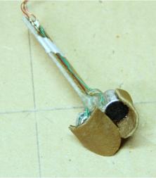
Here some tests in the attempt to "perturbate" the path of the sound wave:

...and the final result. Note the small tubes oriented back-to-back. The circuit is suspended by wires made out of latex, glued on two brass rods shoved into two bores in the PMMA machined base. The two tubes were then locked with the circuit board with epoxy resin.

Since the input of the camera is unbalanced, the schematic of the circuit is very simple. The trim pots allow to balance the amplitude of the signal when both capsules receive the same sound coming from central direction.

Difference in amplitude is tested in a small anechoic chamber with a couple of good quality loudspeakers with sinewave signal.
Once at far left, and then at far right. The result is approximately the same. Note that for the sake of better readability I
retouched over the original traces with a drawing tool because the original image was too dark.

Below some phases of the construction and the assembly diagram.


—— Thanks for reading ——
Don't miss next post
Subscribe to stay up to date when new articles, videos or other contents are available.
RELATED ARTICLES
RECENT ARTICLES


 Subscribe
![Validate my Atom 1.0 feed [Valid Atom 1.0]](../valid-atom.png)